1:100 ‘Performance Centre’ Cross Section Model by Philip Lam

Philip Lam explains to us how he used his model to convey his ideas for increased space and performance capacity:

Phil Lamm (1)

“On a site with limited space, my design tries to increase the audience capacity of a performance centre. The main space is found underground while the introduction of an outdoor space sits on top. The exterior space has been designed to respect and interact with its surrounding buildings.
The idea behind this model was to communicate and understand the spatial and structural qualities of my design.
As part of the brief, our tutors asked us to include a staircase and double volume room. By making a sectional model, it is possible for a viewer to see these components as well as help understand the use of space inside. Also by modelling a section cut, my buildings load bearing structure had to be modified to allow for missing components.

Phil Lamm (2) The material primarily used in my design is concrete. To mimic this in my model, I used laser cut MDF covered with spray painted sandpaper. Rather than making a mould and casting it, this was a quicker and more economical representation of the textural and structural qualities that were required. The half-arch was made using plywood blocks which were stuck together, cut and shaped using the band saw and bobbin sander. The grain in the plywood helped replicate brick and mortar. For the seating, I needed a material which is thin, yet strong enough to sit on the wooden support frames and decided on using mount board. Finally, I used laser cut frosted acrylic pieces to represent the translucent cladding found in my design.

Phil Lamm (3)

By making this model, I have gained further experience working with new materials, tools and techniques. I have realised that using the laser cutter is a fast and precise way to cut materials, but it can also slow you down if there are errors in measurements and tolerance. Careful planning before starting is essential. I really enjoy the process of constructing a good considered model and it is invaluable in further helping evaluate my design.” 

IMG_8786

Philips project pays attention to construction detail and his considerations with regard to material constraints and component accuracy come across well. It’s great to see turning points in project and there were several such points in this one. Philips model threw up issues such as floor levels and door placements that, once evident, were resolved through further making. We look forward to some more projects from Phil next year!

IMG_8791 IMG_8807 IMG_8812 IMG_8822

‘Arch Game Lab’ 1:50 Cross Section Model by Estelle Xin Yun Ang

DSC04032

First Year Student Estelle Xin Yun Ang has just completed a 1:50 section model of her proposal for the re-purpose of vacant space under a railway arch way. Estelle kindly described her project for us:

“I chose to build a model in which part of the facade was removed to communicate the details of interior spaces and the assembly of structural components. The railway arch was modelled as a section to show how it acts as the ceiling of my design. I modelled the underground and made a window to give a good view into the basement. The facade detail was quite important in order for me to express the sense of gaming, which was why I took the time to paint the tiny offcuts.

DSC04082

The exterior spaces surrounding my design is extensively graffitied which inspired me to design a gaming studio where the potential of play is explored. I incorporated game buttons into the design of the facade to convey my idea of gaming.

DSC04092

To model the context, I decided to use plywood as the texture provides a good representation of the brickwork for the archway. For the ground/base, I used mdf wood and applied wood stain to give a good contrast to the light coloured arch. I spray painted the laser cut mdf in grey to show the concrete floor plates. For the walls I chose to use vac-formed styrene to achieve a permanent curved shape. I added strips of acrylic between the two pieces of styrene to make up the thickness of the wall and that helped save some material.

DSC04120 DSC04139


I overcame the difficulties of modelling the curved shape of my design and I have learned to use different techniques on different materials to achieve the best result. After a few trials and errors I was able to understand the construction of my design. This is what I find interesting because there are so many ways in making a model and through experimentation I get to know which method works best for my design.”

IMG_8220 IMG_8226 IMG_8228

What is clearly shown in this model is the attention to making each element correct for assembly. This patience and consideration is something we should all aspire to when designing and making. Often one of the hardest things to do during a project is accept that something you have made is incorrect and should therefore be re-made. Whilst this may seem like wasted time it is exactly the opposite and by taking a step back from the project to look at what you have learned you will see that such mistakes are necessary for your own understanding of the design as well as gaining a better understanding of material and machine constraints when making.

We hope to see more projects with this level of thought and consideration in the coming weeks leading up to the final submissions and in future first years.

IMG_8259 IMG_8262

Stockport Site Massing Model by Finbar Charleson

This project looks at a site sandwiched between exiting buildings and natural boundaries in Stockport centre. As with most of the projects I have seen Fin work on it’s great to see someone using a variety of media on their desk to inform the decisions in making and in turn use the results to influence their ideas.

As the site includes several large tower blocks it was decided to create the masses as hollow boxes to both save on material and weight of the completed model. The box sections seen here were carefully made up from planes of material – most of it scraps from other projects. 

Once again being concious of material use, Fin designed his contour base to be laser cut into steps with supports as opposed to entire sheets. This again saves material and overall weight. The process requires some minimal extra consideration when producing drawings but the savings are great and well worth the effort. Read more on this method of construction here.

To create the imposing and dominating viaduct feature which spans across the site Fin chose to use a solid mass created from pine. The arches were drawn out and rough cut on the bandsaw before being sanded smooth.  Legs for the viaduct were created as separate pieces with varied heights depending on their position across the contours. The legs were then clamped and glued over night.

Finbar gave us a few words reflecting on the project so far:

‘The model has helped to negotiate a complicated landscaping condition, in that the envelope links three different levels: water, ground and the 1st floor gardens, of a proposed Waste Water Treatment Plant in Stockport city centre. The context is modelled with traditional craft methods as I feel the site has a great sense of history, including the famous  Stockport Viaduct. It has helped to explore sensitive ways of repurposing existing warehouses I used Pepakura software to produce nets of meshes generated in Grasshopper for Rhinoceros, for the initial massing proposals.
The next step is to combine the spatial arrangements of the building with environmental analysis and try new massings on the same model.’

The completed model has a removable site section to allow different proposals to be inserted into context. Fin has already made several suggested forms from card as seen below. Finbar Stockport Model (15) Finbar Stockport Model (16)Finbar Stockport Model (18) Finbar Stockport Model (17)


Runcorn Reprogrammed Master Plan, Constantinos Papaioannou

Year 6 Re_Map Student Constantinos Papaioannou has just completed this master plan of his study area looking at Runcorn. The model will be used as an overview of the entire site with more specific site study models to follow.

The model used a minimal amount of Laser engraved and cut MDF combined with site focus areas represented with red coloured acrylic and frosted clear acrylic.

Constantinos produced the model in just a day and a half. We look forward to seeing the next stage of the project!

Urban Spatial Experimentation project, 5th Year Project

5th Year Projects (6) This 5th Year group have spent the last few days putting together a 1:500 site context model of the area they will be focussing on for their individual projects. The project is called Urban Spatial Experimentation or U.S.E. The site in question is the Albert’s Shed on the River Irwell and the model will allow different proposal models to be placed in context as they are developed. 5th Year Projects (7)The model consists of several mixed media that are used to represent different aspects of the site. It was quickly decided that the offsite context buildings would be represented using jelutong block offcuts to reduce the cost and effectively put the massing of each building together. Building footprints were drawn out and placed on the block pieces which were then cut to height before being shaped and sanded to finish.

5th Year Projects (10) 5th Year Projects (9)

The main base of the model is made up using 2mm MDF which was laser cut and engraved to create the minimal contouring on the site and provide the relief from the river section which was added last as a piece of black acrylic.

5th Year Projects (5)

5th Year Projects (11)

The group used small seed pods from a tree to represent the trees across site. This technique was used last year by several students and can be seen in this project by Laura Minca.

Here are a few pictures of the finished model below.

PA280304 PA280309 PB250557 PB250558


Abhi Chauhan: ‘Testing the Machines of a Third Industrial Revolution’ 1:100 Site Section Model

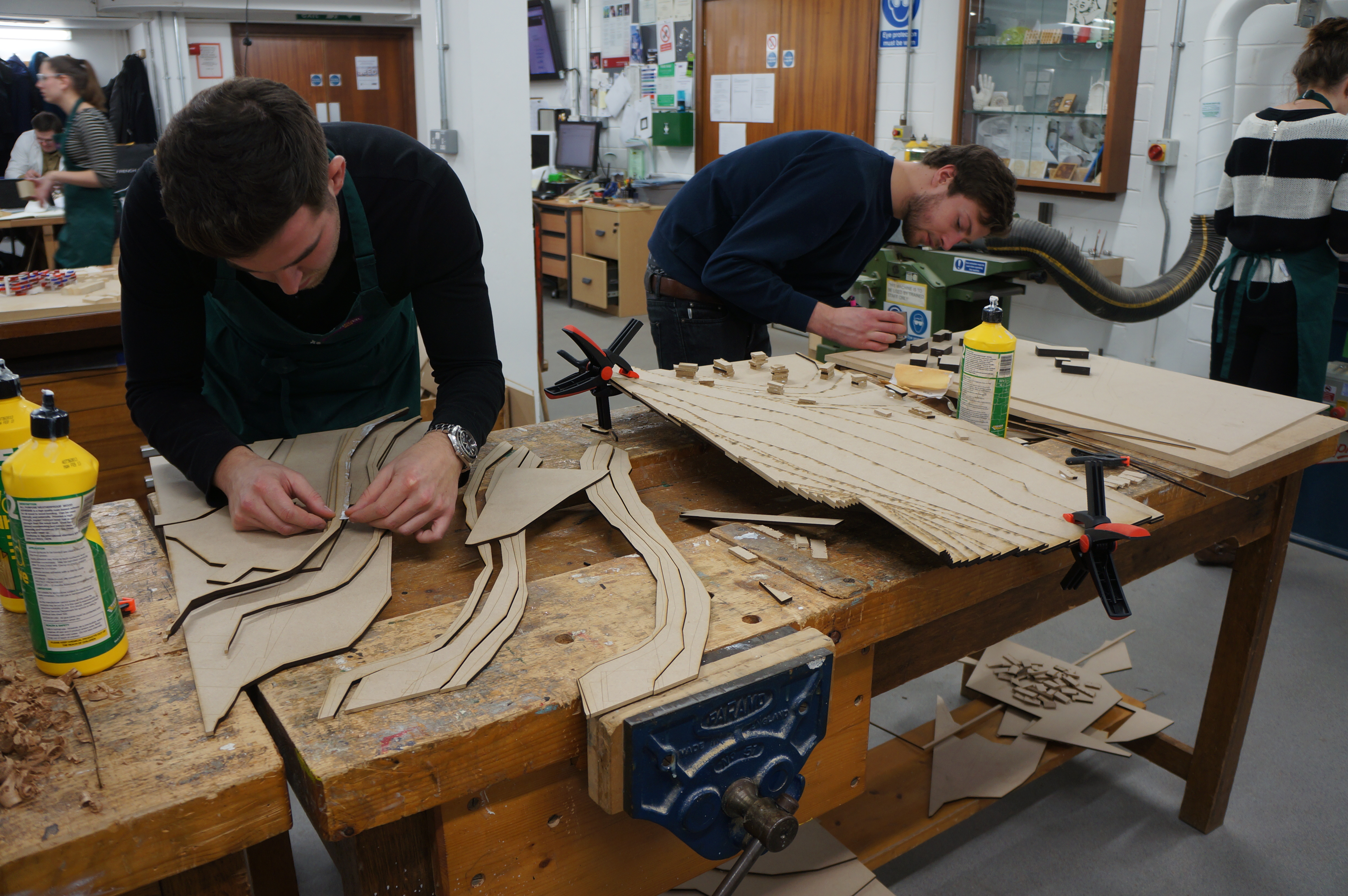
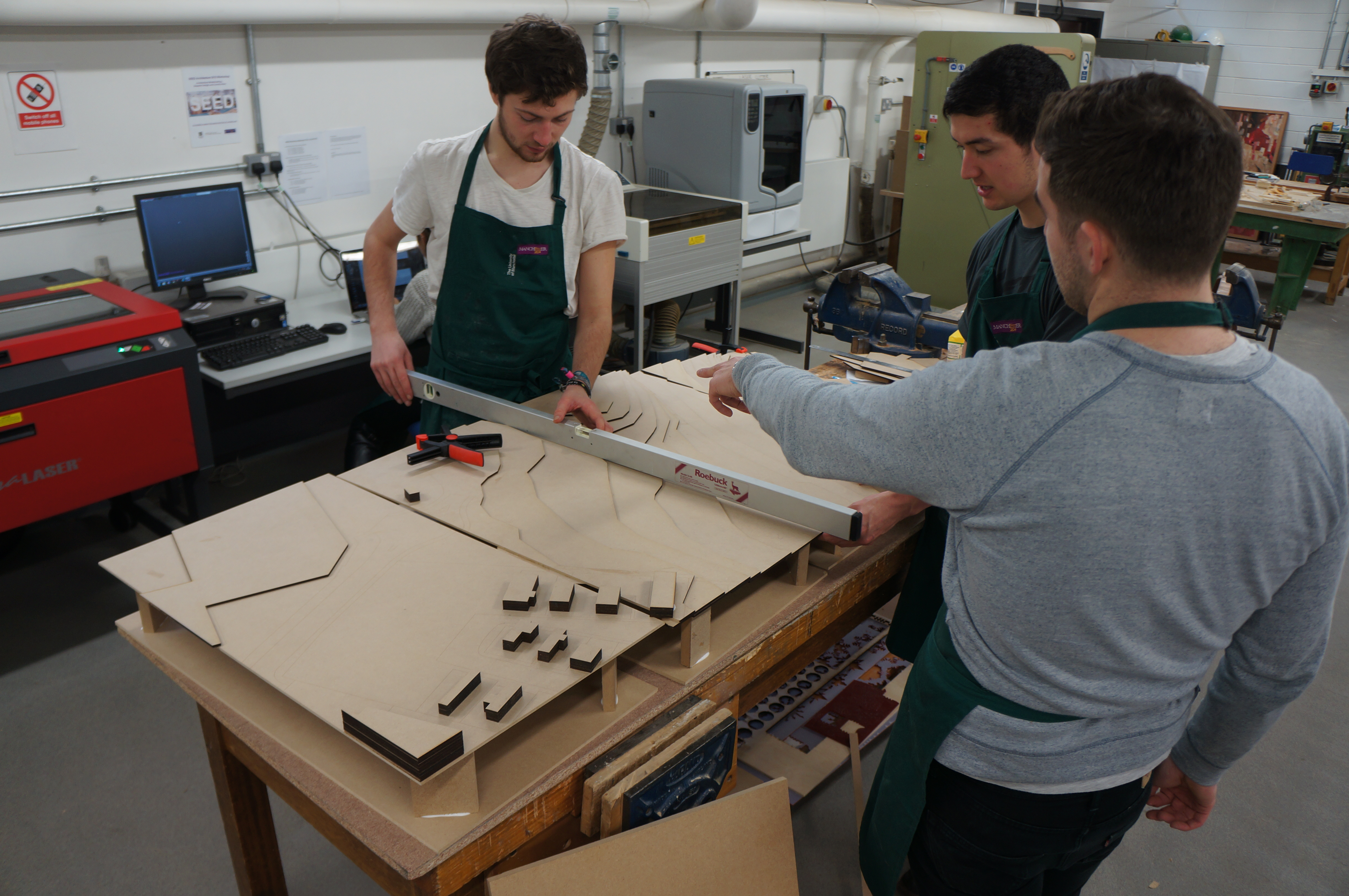
6th Year MArch student Abhi Chauhan has recently completed several models as part of his Intimate Cities project. The earlier models were used to demonstrate initial concept ideas and helped influence design changes. In keeping with the subject matter of the proposed development Abhi has put heavy emphasis on digital manufacture.

Abhi gives us an over view of the project and how this model fit in to its development:

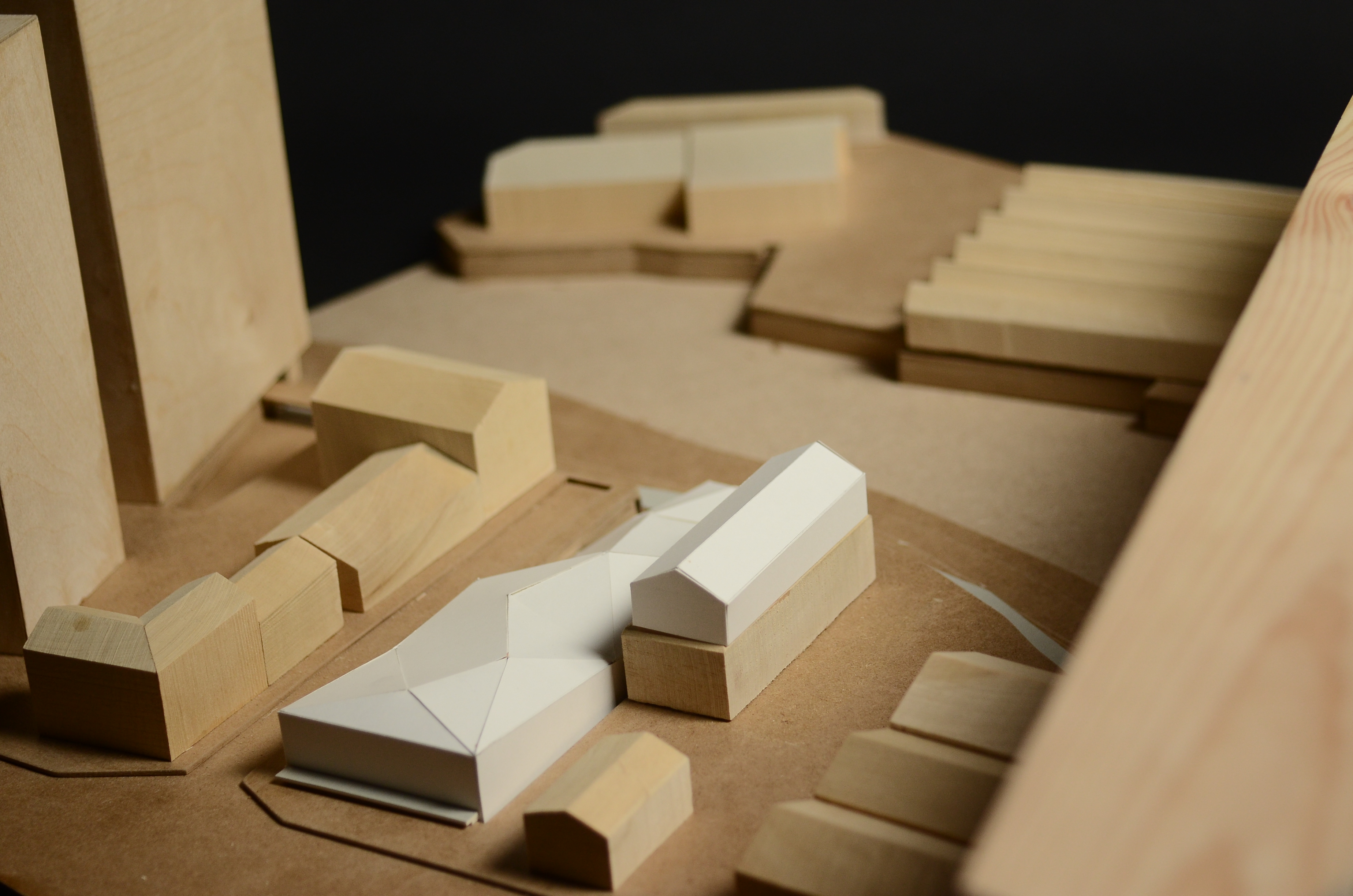
As part of the Intimate Cities Atelier this year we were concerned stalled construction sites in the city of Manchester. These sites are unique in that their infrastructural order has been partially installed and my primary aim is the reconnection of these sites back to the city context. Situated on the Potato Wharf stalled construction site, the final scheme looks at the idea of bringing around a Third Industrial Revolution, by looking at the research and testing of an advanced manufacturing technique (3d printing) and a new energy infrastructure, (hydrogen fuel cells).

 Realised as a masterplanning strategy the stalled concrete frame on the Potato Wharf site is used a ‘live’ test-bed for 3d printed architectural components, in addition to this the scheme engages with the redundant  transport infrastructure bounding the site and reinstates the canal and rail network as a distribution matrix for the transport of raw material. A reconfigurable 3d printed public park defines the edges of the new site in the overall strategy.

VISUAL LIGHT

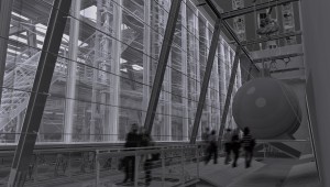
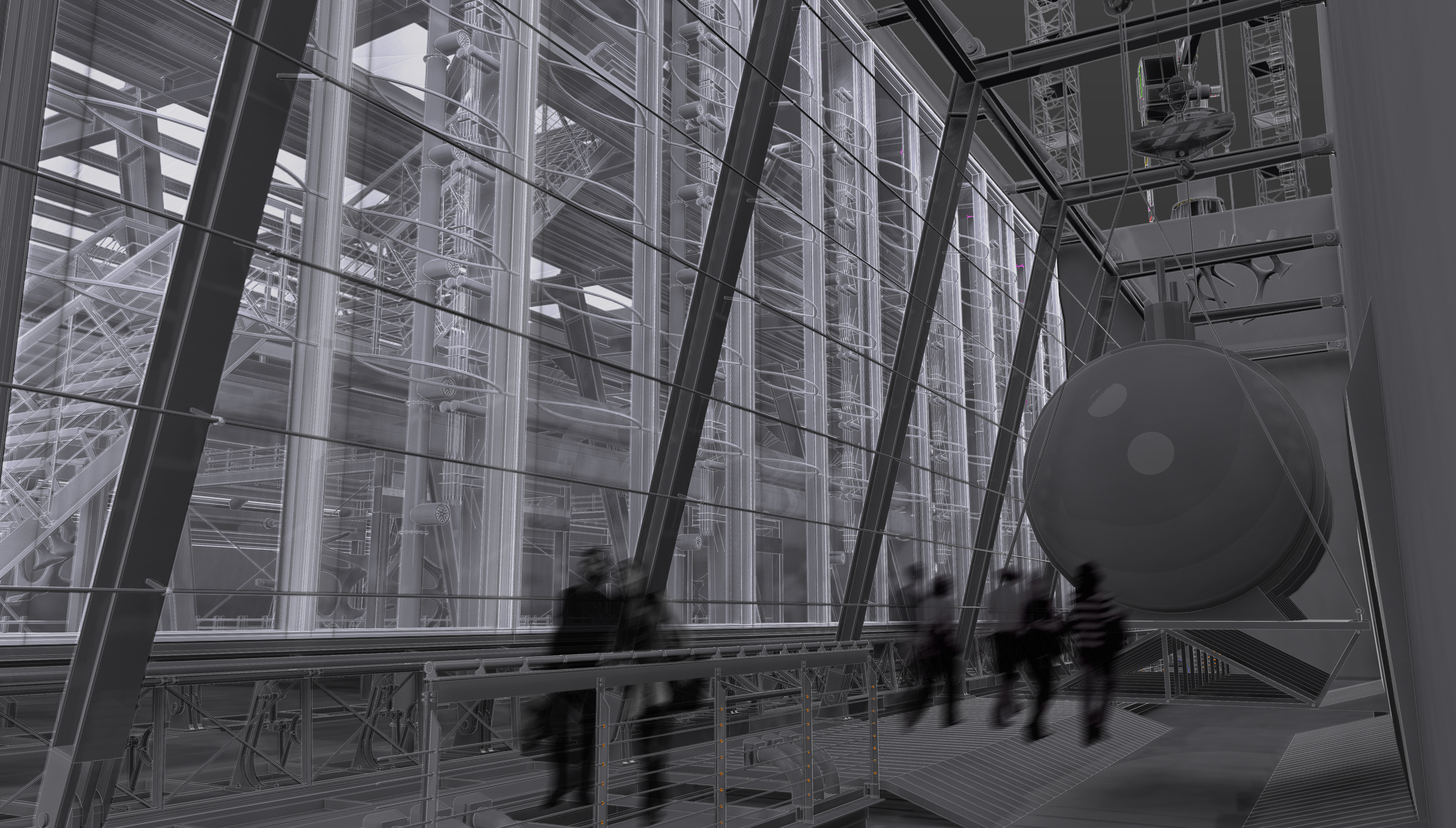
The renders depict how the main 3d printing manufacturing hall and hydrogen exchange will look. The 3d printing facility is concerned with the research, manufacture and testing of 3d printed architectural components and as such the construction and detail is oversized to deal with a variety of different scales present on this project.

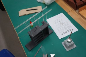
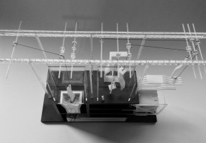
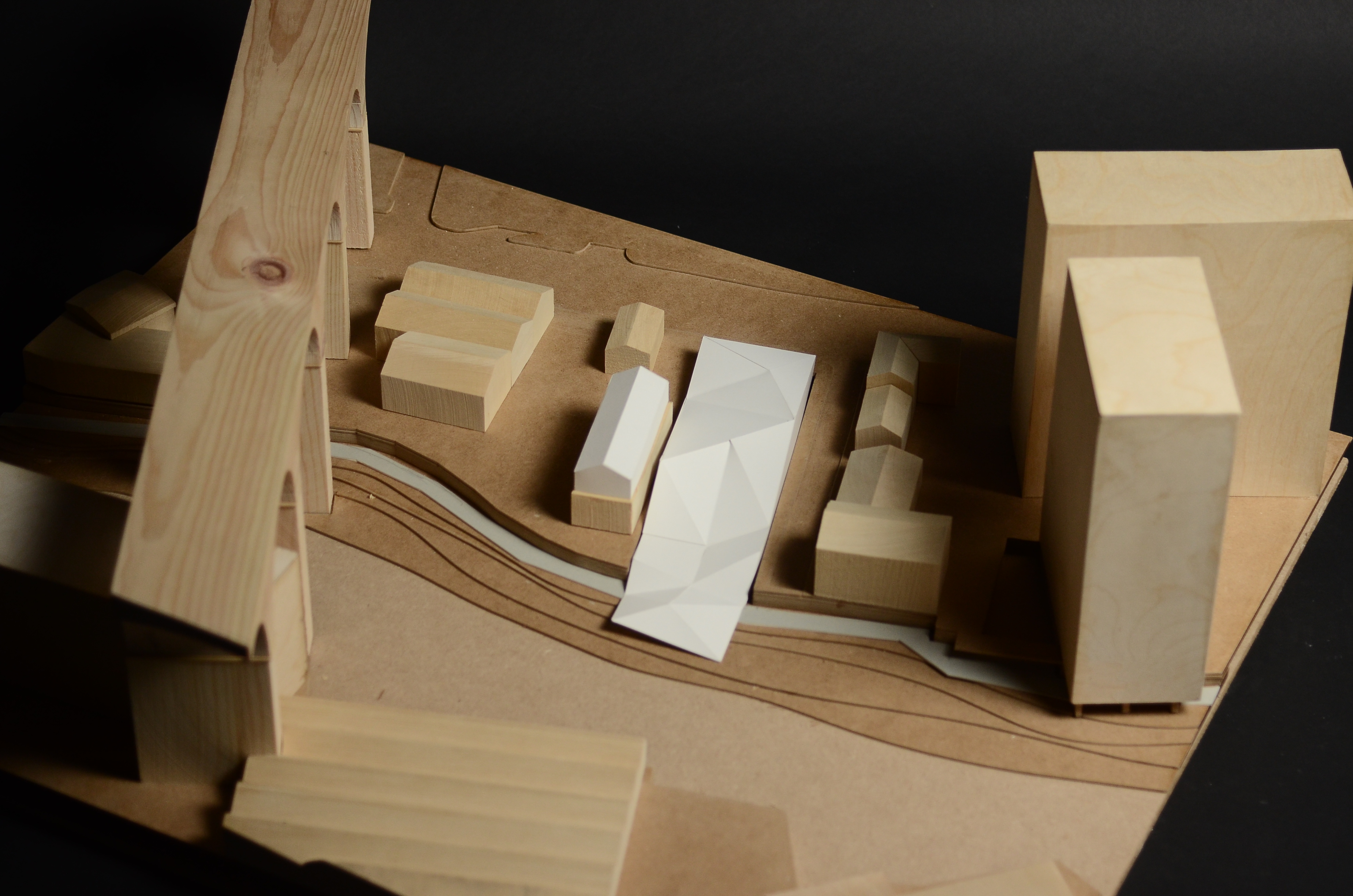
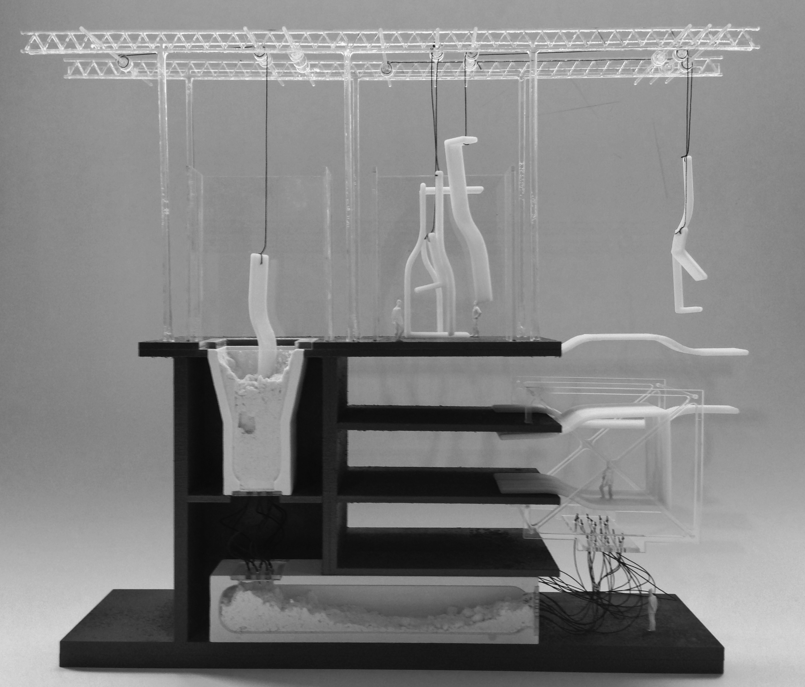
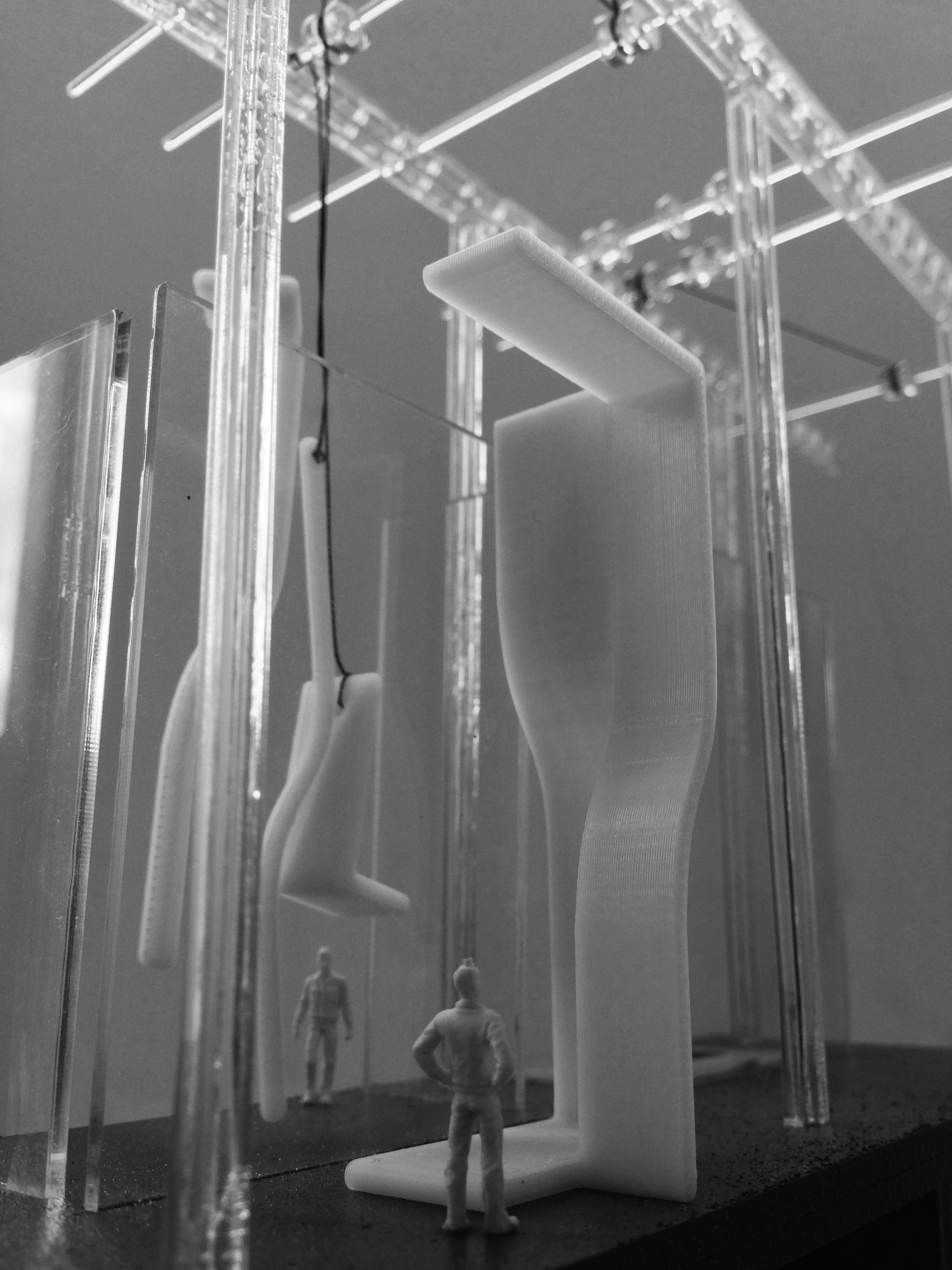
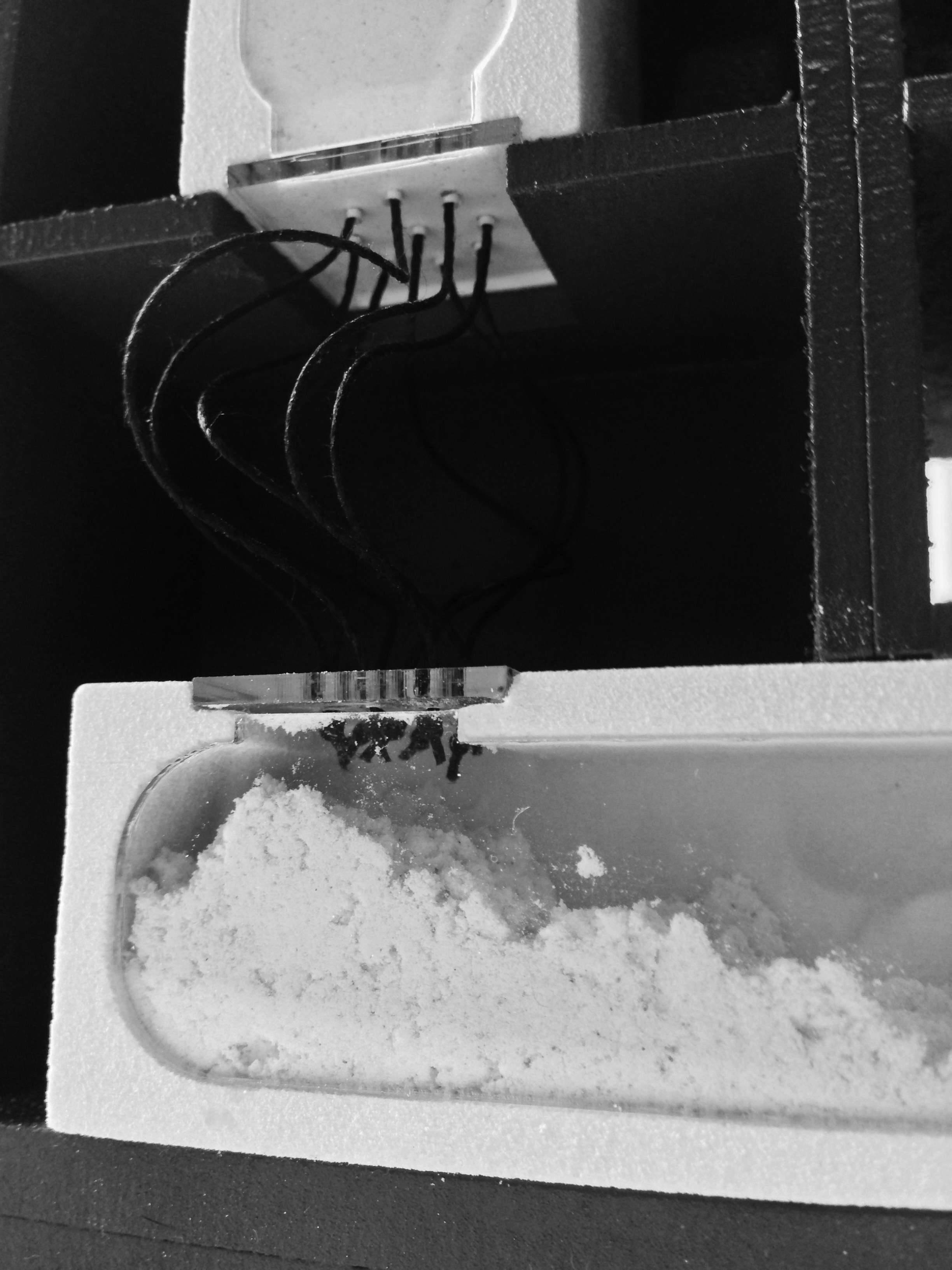
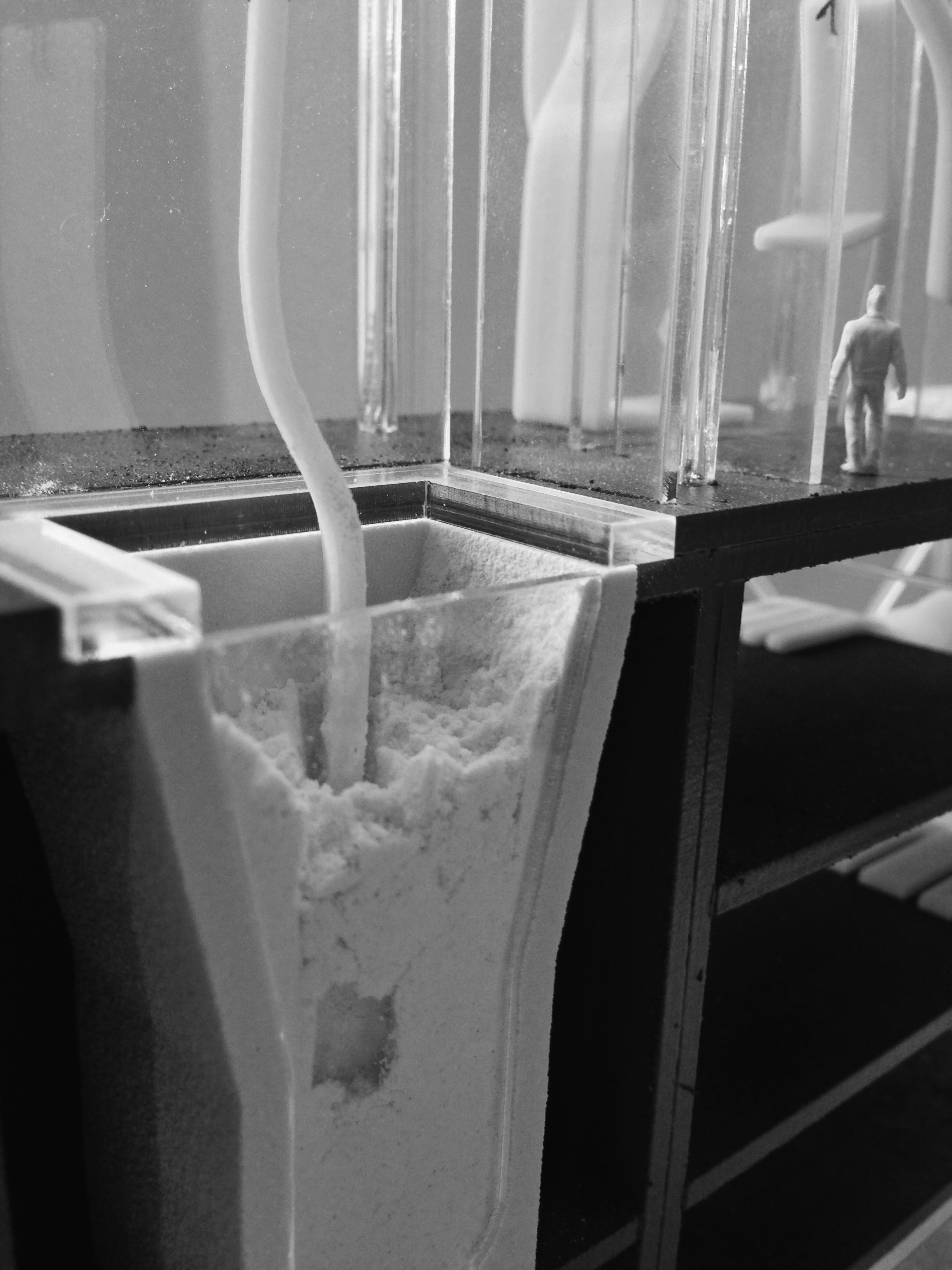
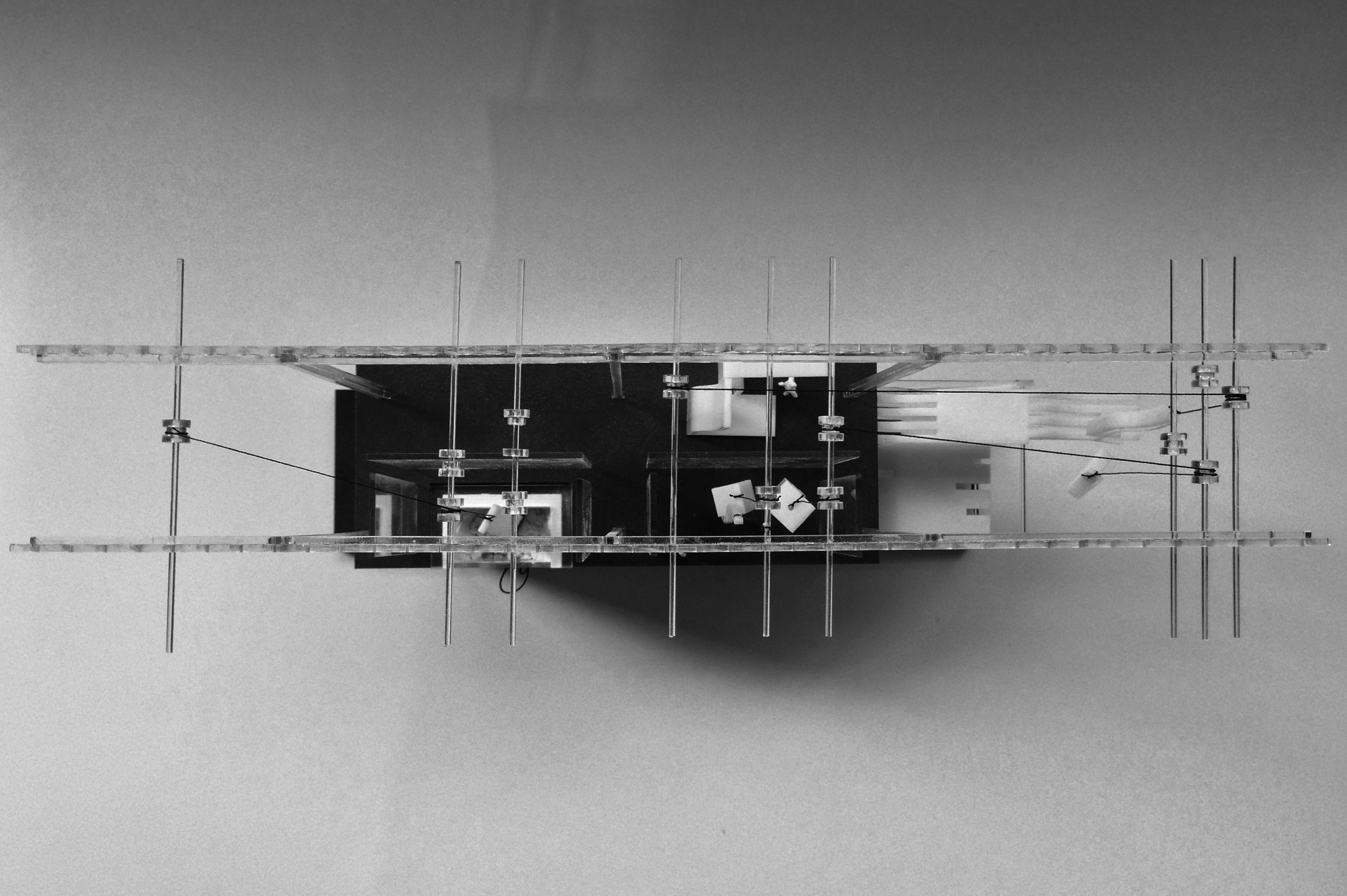
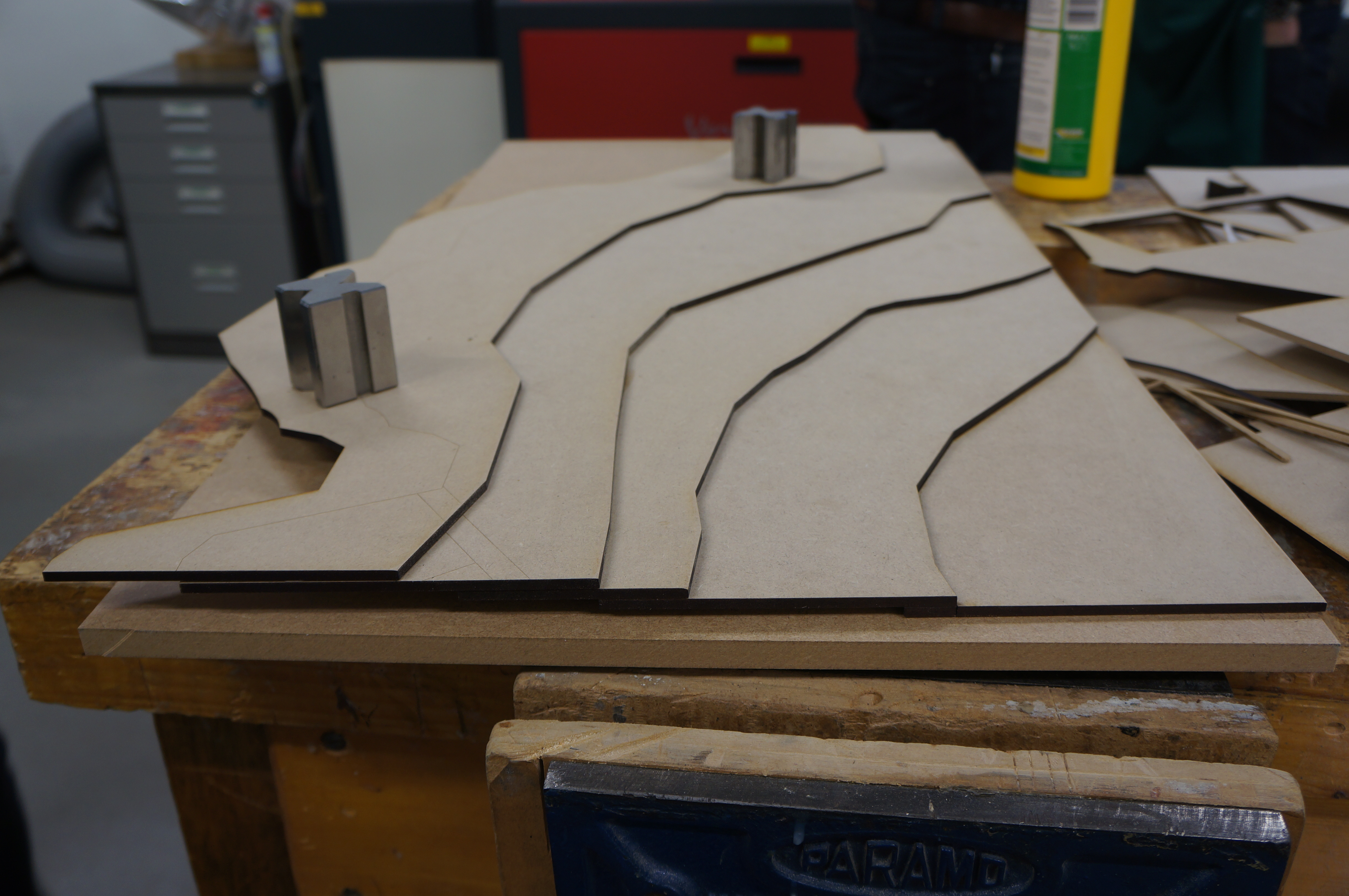
This first conceptual model depicts the main processes occurring in the 3d printing facility and follows the life-cycle of a 3d printed architectural component from its raw powdered state – stored in a material archive; to the printer beds; then for reconfiguration in a graveyard of failed components; and ultimately to its reverse engineering back to its raw powdered state.

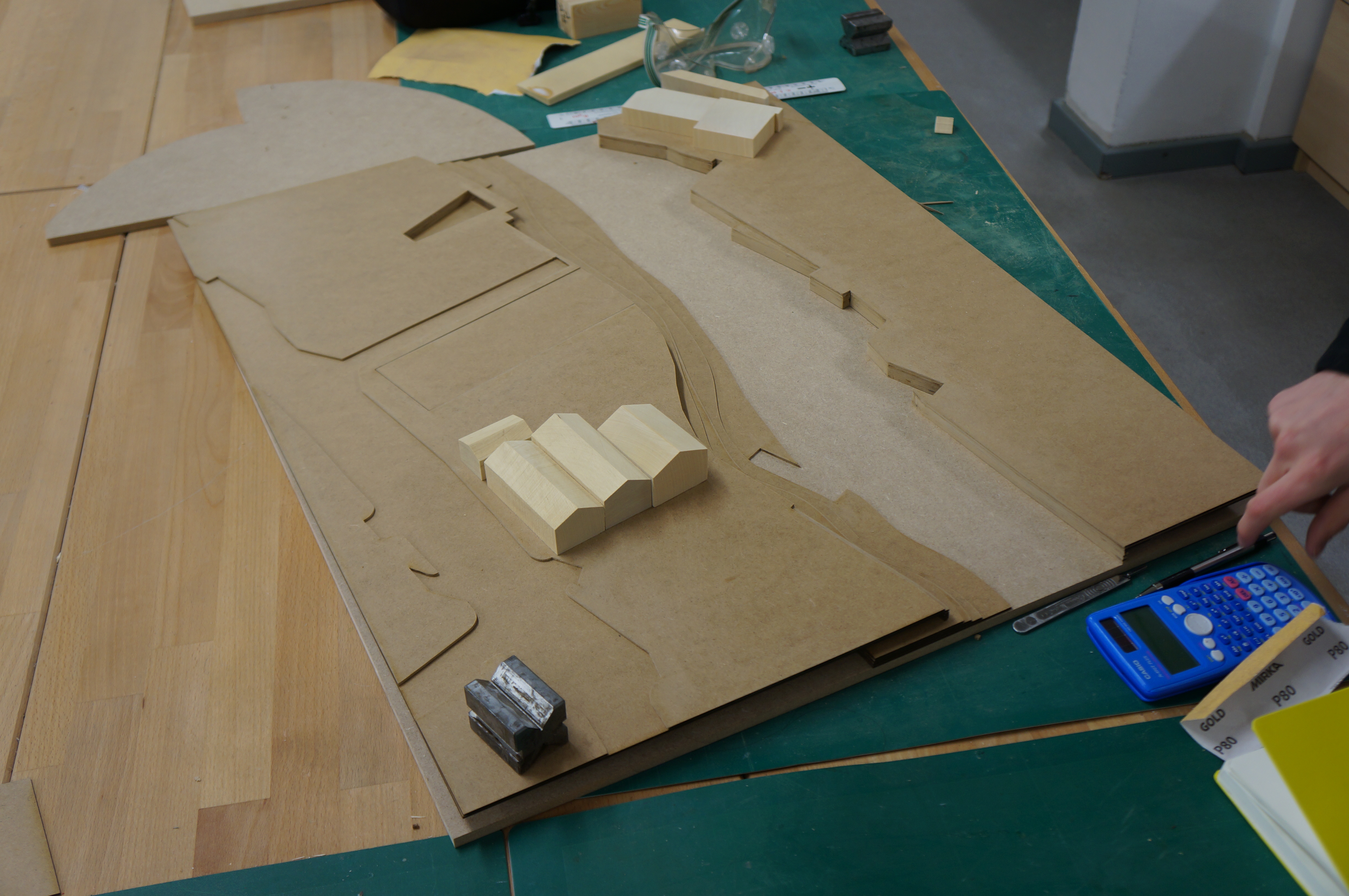
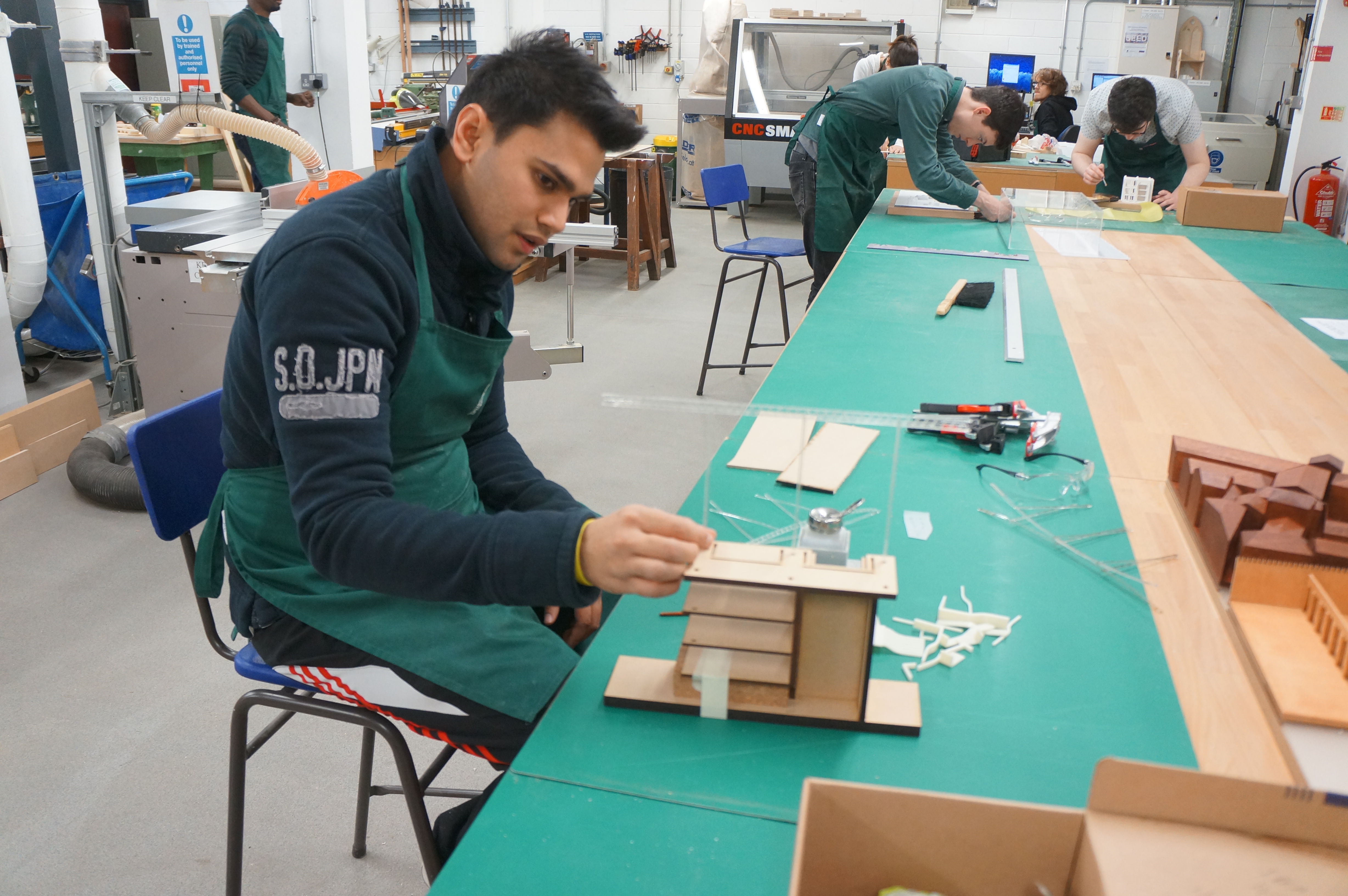
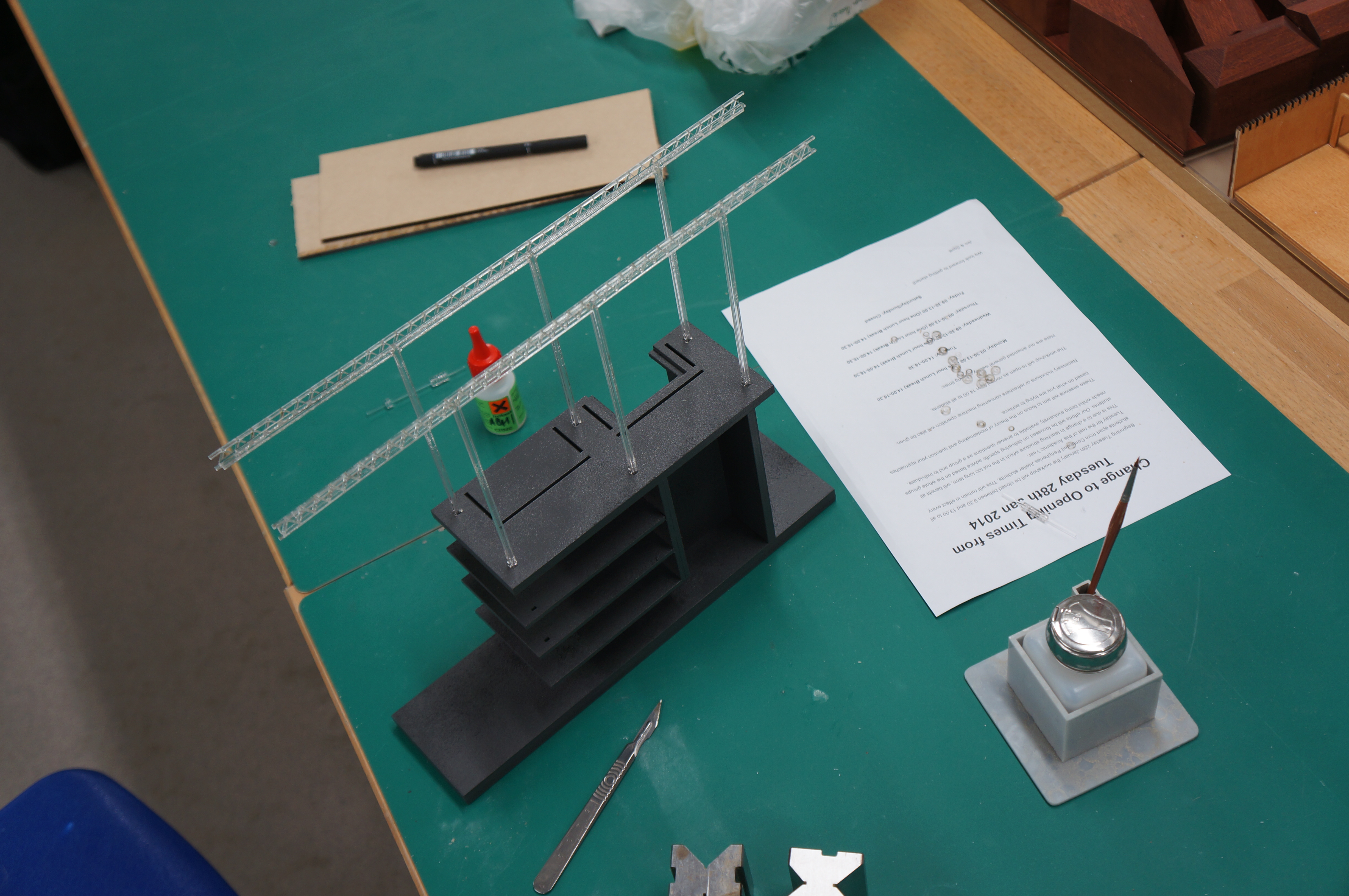
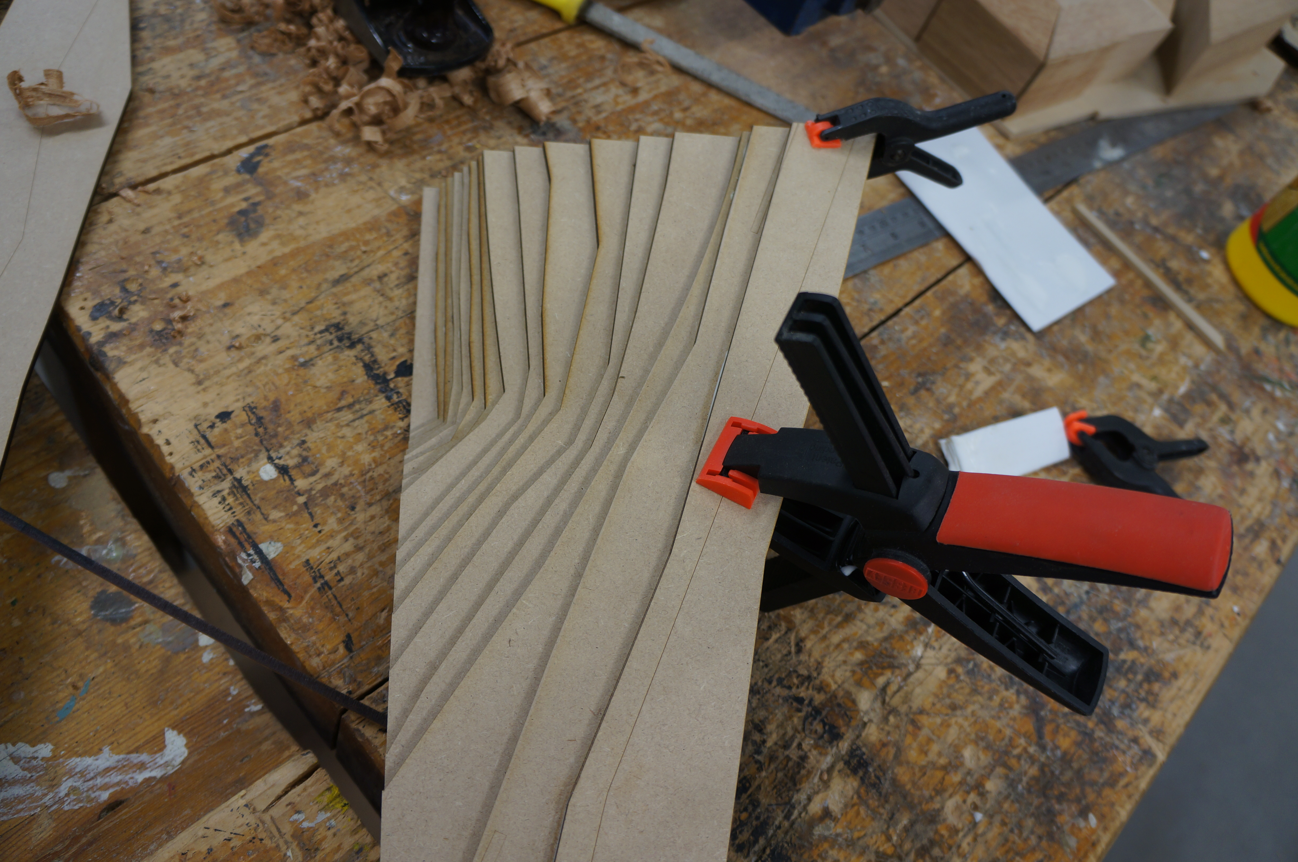
The main frame was laser cut from 6mm MDF and designed to slot together. After spray painting grey to depict a raw concrete surface a series of powder printed material stores were fixed in place. It was decided to 3d print these stores due to their complex shape and the desired ‘layered’ construction aesthetic I was after.

The main machines in the model have all been constructed from separated components each laser cut from 2 and 3mm clear acrylic.

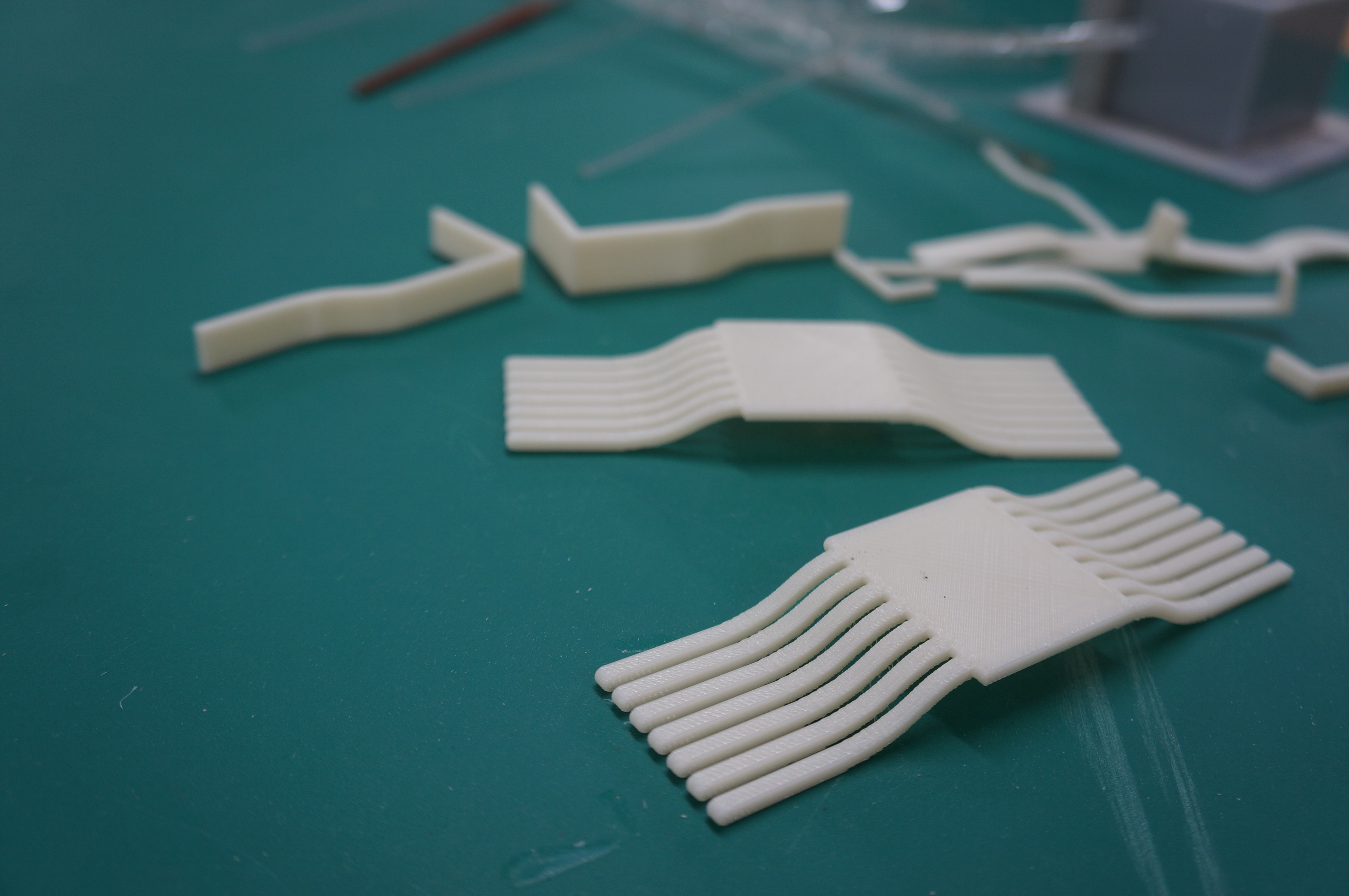
The 3d printed architectural components created in the facility were depicted by themselves being 3d printed. These parts were modelled in 3ds max and made ‘watertight’ ultimately for 3d printing on the ABS printer. (Abhi Chauhan May 2014)

Abi (2) Abi (5)Abi (6)

Abi (7)

One aspect of Abhi’s model work which is particularly successful is the appropriate use of different process. Having an understanding of the best suited method to achieve a desired outcome is key to an effective model. Without a clear aim as to what it is you are trying to convey many models have little practical use in conveying the key aspects of a design concept. This model of course naturally lends itself to 3d printing due to the subject matter.
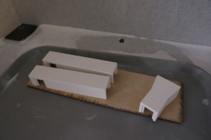
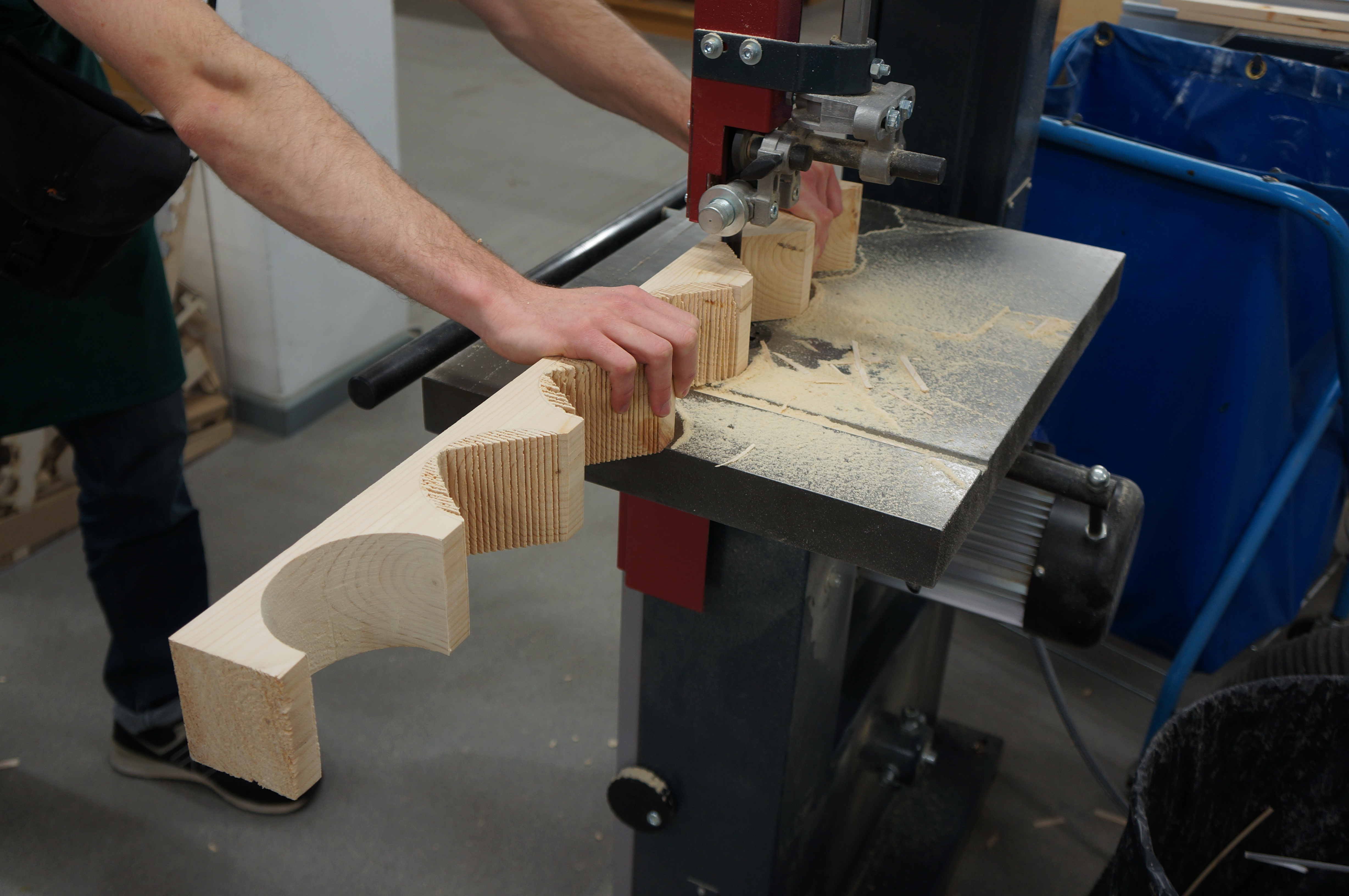
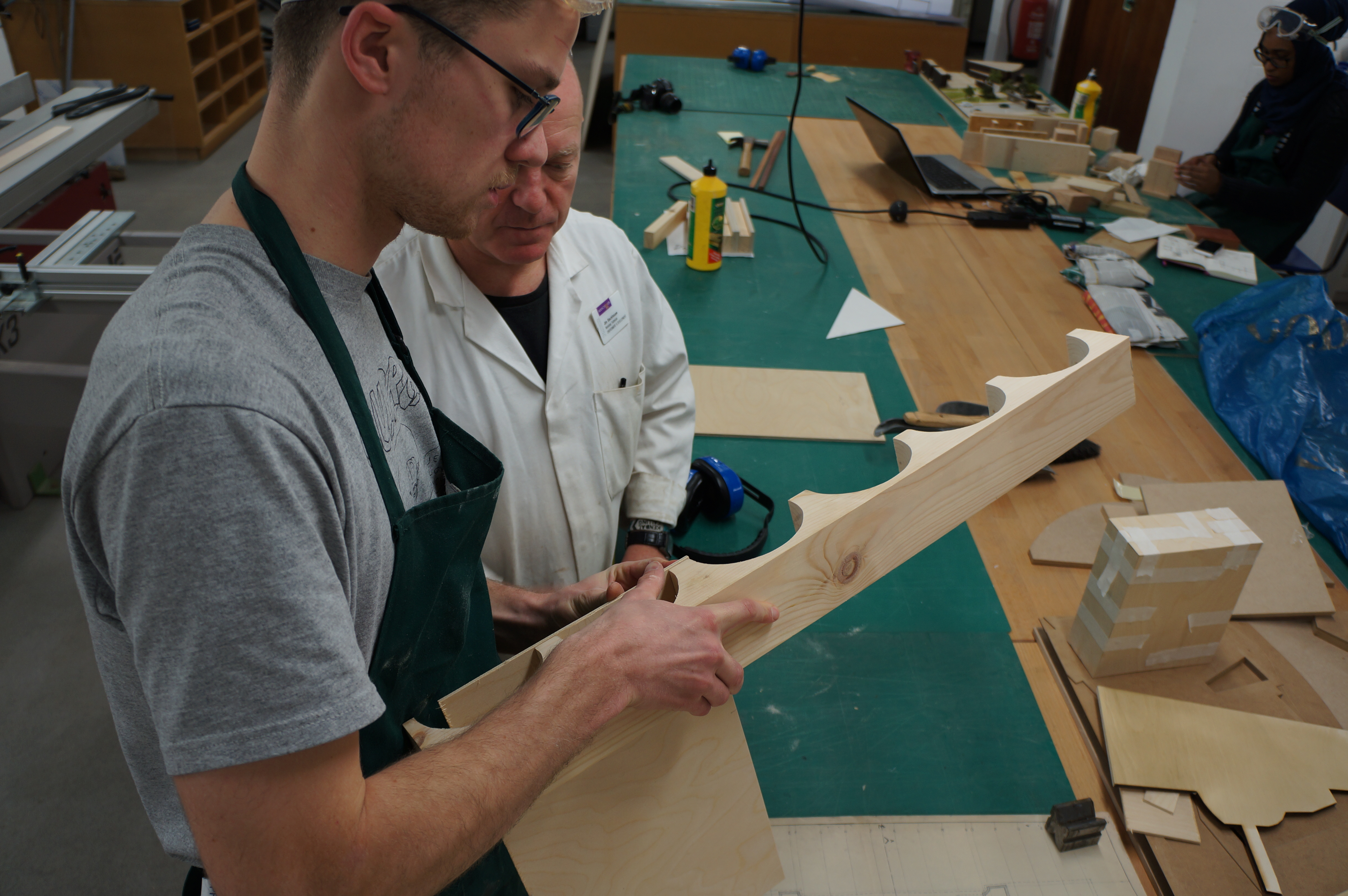
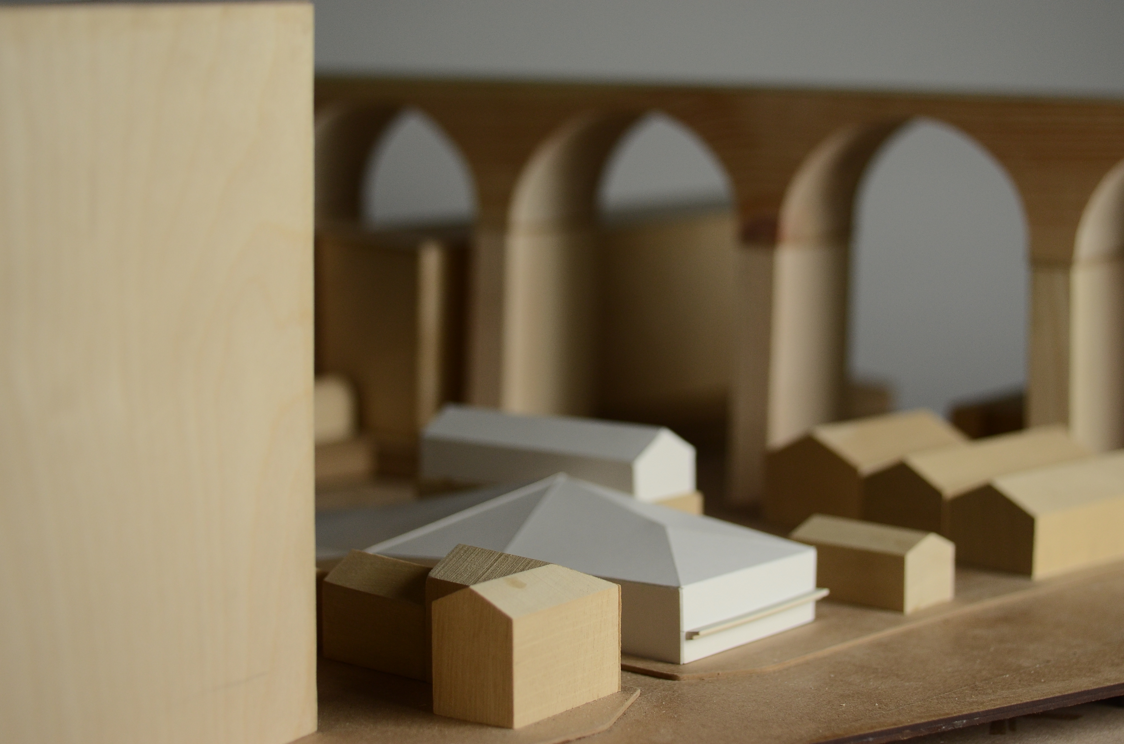
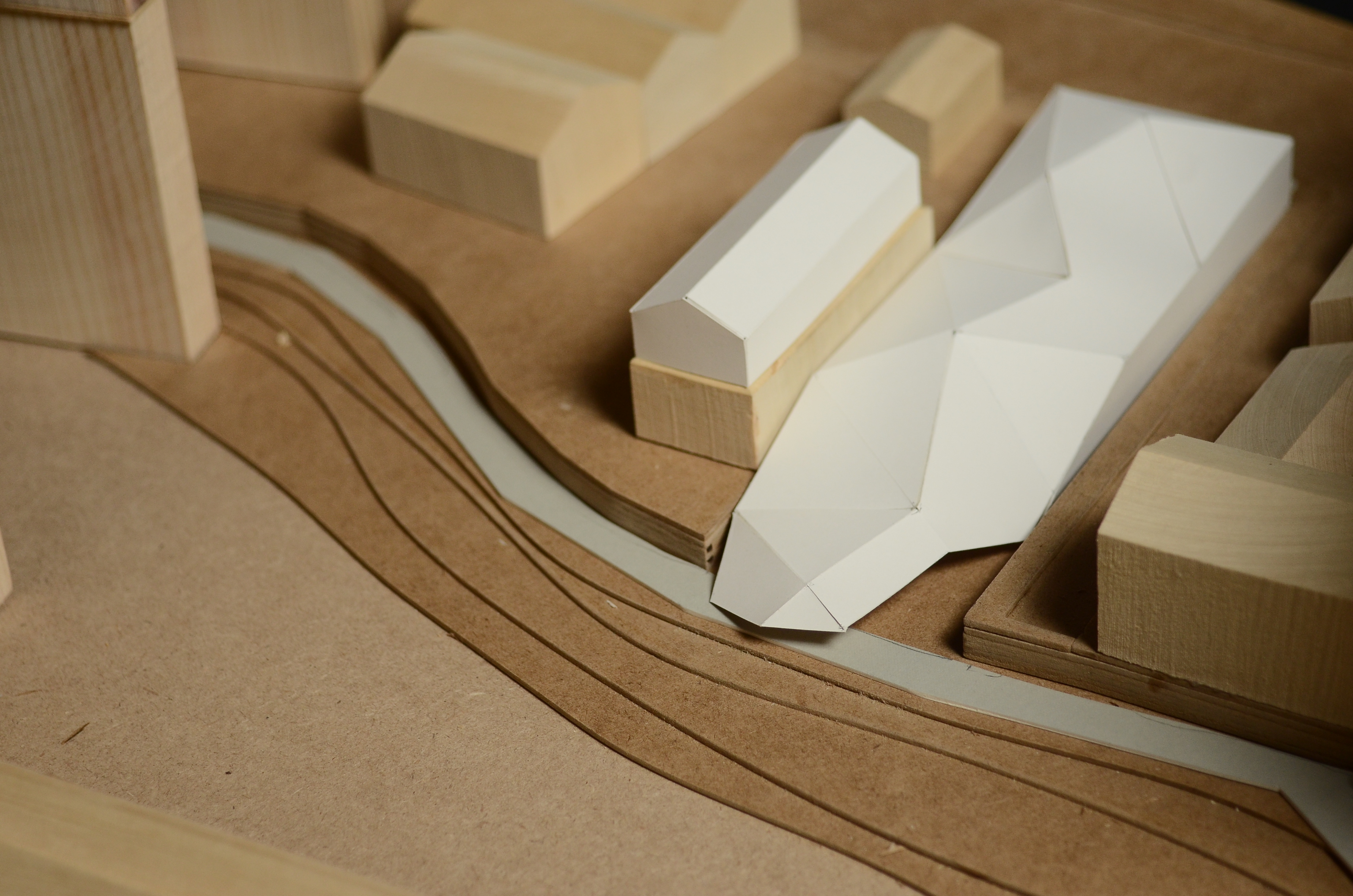
IMG_0740 IMG_0744 IMG_0750 IMG_0752 IMG_0753 IMG_0757 IMG_0758

Hurva Synagogue in Jerusalem, First Year Paradigms Project

This first year group have made a great set of models to demonstrate the various design considerations used in this Louis Kahn design. The building was designed in 1969 but never built.

DSC02268 DSC02271

The group decided to produce a 1:50 section model showing the internal construction. This was achieved through a combination of laser cut and hand made components. The original design proposal was to be made from stone and would appear consistent throughout. For this reason the group decided to make the model’s using wood with light staining to blend the lighter timber with the MDF sheet.

First Year Louis Kahn Architects study (26) First Year Louis Kahn Architects study (28) First Year Louis Kahn Architects study (31) First Year Louis Kahn Architects study (33)

The groups 1:100 model (below) shows the extent of the proposed completed building. The group used pine to cut the outer wall components which were stained. A nice feature of this model is the ability to remove the roof sections to view the internal layout.

First Year Louis Kahn Architects study (44) First Year Louis Kahn Architects study (43) First Year Louis Kahn Architects study (39) First Year Louis Kahn Architects study (38)

This is the groups site plan model demonstrating its relationship geographically to the nearby mosques which had be a key element of the design from an early stage. The line of sight is shown using red thread across the landscape.

First Year Louis Kahn Architects study (49) First Year Louis Kahn Architects study (50)


City Tower Project, 1st Year ‘Group 8’ Paradigms Project

This first year group, also looking at the work of Louis Khan, have been looking at the un-built City Tower Project. The design was  intended to be built in Philadelphia in the 1950’s but stopped after several stages of development. despite this it is still regarded as an important study and influenced future designs with its use of space frame technology. (Albani, 2013)

DSC02242

The group used laser cut floor and base plates to build the structure around central wooden dowels as the building core. The outer ‘web’ skin the binds the floors was represented with string threaded through pre cut holes in each plate.

DSC02246

DSC02260 DSC02259

The group used our new studio space to photograph the model against a white backdrop.

First Year Louis Kahn Architects study (18) First Year Louis Kahn Architects study (19) First Year Louis Kahn Architects study (21) First Year Louis Kahn Architects study (22)

As several people pointed out, the addition of scale people and cars really help to convey the size of this design to the viewer.

DSC02265

Albani, City Tower, Architects,Architecture,Architectuul, [Online Article] Available from: http://architectuul.com/architecture/city-tower , 2013

Trenton Jewish Community Bath House, Antoinette Y. Oni and Paul Wright, First Year Paradigms Project

This first year project looks at the work of architect Louis Kahn and his Jewish community Bath House design for Trenton, New Jersey constructed in 1955.

DSC02249 DSC02253

An important part of the overall design was the inclusion of the surrounding landscaped and wooded area. For this reason particular attention has been paid to the representation of each tree on the site using the abstract use of wooden dowels.

First Year Louis Kahn Architects study (3) First Year Louis Kahn Architects study (10) First Year Louis Kahn Architects study (12) First Year Louis Kahn Architects study (13)

How to Save Money and Materials when Making Contour Models

Just before the Christmas break I made a post about the benefits and importance of concious planning and material consideration when thinking about your models. Here is a great example carried out by a group of 3rd year students over the last few days.

This group set out to produce a contour model of a site they have been given to focus on for redevelopment. They took the time to approach us before starting to plan their model which resulted in a huge saving for them in cost and in the materials saved.

Rather than using entire sheets of MDF to build up contour layers We suggested they amend their drawing to construct the contours using the ‘step’ method. This means reducing each contour piece to a fraction of the full sheet size with the only non visible area being a small step to which the piece above can be fixed.

Out of the original materials estimate of 25 full 4mm x 800mm x 450mm sheets for the main contour section of the model the amended drawings helped to decrease this number to just 6.

At the current cost of £2.50 per sheet, the original cost of material for this part of the model would equate to £62.50. After redrawing the file and planning each cut sheet the 6 sheets required cost just £15. A huge saving of £47.50 and 19 full sheets of 4mm Medite MDF.

As you can see it is well worth taking the time to evaluate what it is you are producing and the necessary material required. A good place to start is with your tutors, Jim and myself who are dealing with this subject matter everyday.

Scott