Modelling with Planning – 1:20 Detail Case Study

During the last academic year 5th year MSAp Group undertook a 1:20 detail study project to explore the relationship across a threshold junction between old and new. The Project was a great success and provides a great example of a well organised and applied use of modelmaking. A big thanks to the group who kindly responded to some questions we put to them as follows.


This model was a 1:20 sectional detail showing a threshold junction of a semi-detached house, displaying how a new annex (porch) module meets the old, non-traditional construction of a 1920s house.

Our aim was to use materials that would be close representations of the materiality applied in the construction of old to new. When planning materials, process and overall time management of the model, we created a ‘strategic planning matrix’ (below), identifying the proposed material, dimension, sourcing of material and costs (filled as we went along). The planning and sourcing of materials helped organise our time efficiently. We divided model-making processes into two parts, making components and assembly. The overall experience expanded our model-making skills, introducing many of us to new forms/ways of making.

To enable efficient team working under the time constraints of the workshop opening hours, we clarified roles and tasks daily. This helped us manage the workload and distribute tasks of the our project accordingly, therefore not all group members were always working on the model in the workshop, but on other areas of the project. A continuous level of effective communication enabled all our team members to work productively. This gave us the opportunity to explore a trial and error approach whilst making certain components, in particular when moulding and casting. It took a few attempts to get components to the ambitious standard we were aiming for.


As a group, we began planning the model with plenty of time ahead of deadline to ensure room for error, which proved useful during the assembly period. Collectively, we have broadened our model-making abilities/skills, and we were able to add a fine level of detail to the model, adhering to the high standard we set for ourselves, and a level of sophistication.

Overall, we gave ourselves enough time to plan, consider and make – planning and organisation became a very enjoyable task in itself and we were able to take on skills in professional practice which we hope will be applicable to working in a team in the future.

-Meera Lad, Abi Patel, Sean Martin, Danny McBride, Joe Stancer, Jack Williamson. 2018


Cross-Section Modelling

Cross-section models invite us to view a subject internally by exposing construction details that present spatial and physical relationships. The process of making a model in section allows us to be explorative of the fabric elements that are applied to create the overall form in a way that complete site or massing models do not demonstrate.

1.100 model dan kempski (1)

By cutting through a plan we are able represent the supporting framework and foundations of a building and reveal the anatomy of their relationship to the overall form of a design. The scale of section models tends to be best suited at 1:100 or bigger due to the small size of design features at anything smaller. The smaller the scale the more simplified elements become which, when we are investigating structural or building cladding for example, becomes much less informative.

1.50 Maggie

As with all model tasks we must clearly outline what it is the model is setting out to achieve.

The potential variants, materials and methods for making a model mean there is no quick answer to questions about what is right or wrong way to do something. It is up to you to identify what messages need to be conveyed and these messages will determine the approach to making the model.

DSC04247

DSC04091


Example questions to consider:

  • What messages must the model convey?
  • Is it about its relationship to an existing site or the surrounding landscape?
  • Is it there to demonstrate the technology being applied in the design?
  • Are you setting out to explain how a particular material or element of the design relates to another?

Before making any decisions think about this carefully to avoid missing the point or creating unnecessary work for yourself or group.

When looking at these models we need to focus on a specific target area of a plan that best serves our intended purpose or message. If this purpose examines how a wall will support a roof for example then ask yourself to what extent does the viewer need to see the rest of the building around this focus area?

John Soane Model Ketil Rage and Kristian James (1) Katie Williams 1.20


Tips for Cross-Section Modelling

  • APPROPRIATE SECTION. Identify the best place to make your section on a building plan. This should be based on your overall purpose and is the most critical consideration when making a cross-section study. Try not to section areas with excessive repetition of features such as windows that will make for more work when producing the model. Double check your scale!
  • SUPPORT AND STRENGTH CONSIDERATIONS. Don’t rely on glue or magic to support floors or load bearing elements unless you have designed them to do so. Looking at the section in question and considering materials you intend to use you should think ahead to the point when the model should be self-supporting. How will it hold itself up if the other side of the building isn’t there? Thinking and planning the model thoroughly is crucial.
  • UTILISE OFF THE SHELF COMPONENTS. If your section cuts through floor levels you may need to represent supporting beams, trusses or layers of facade cladding. Rather than manufacturing these to suit make yourself aware of materials that are pre-formed such as styrene ‘I’ beams, tubing or textured sheet material. There is no point in making something that is a standardised material for construction much like how you would approach full scale building design to reduce working time and costs.

If you’re unsure of anything you know where we are.

Scott

CiA Year 6 Section (16)

CiA Year 6 Section (12)

‘Urban Mining: The St. Johns Quarter’ 1:100 & 1:50 Models by Daniel Kempski

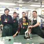
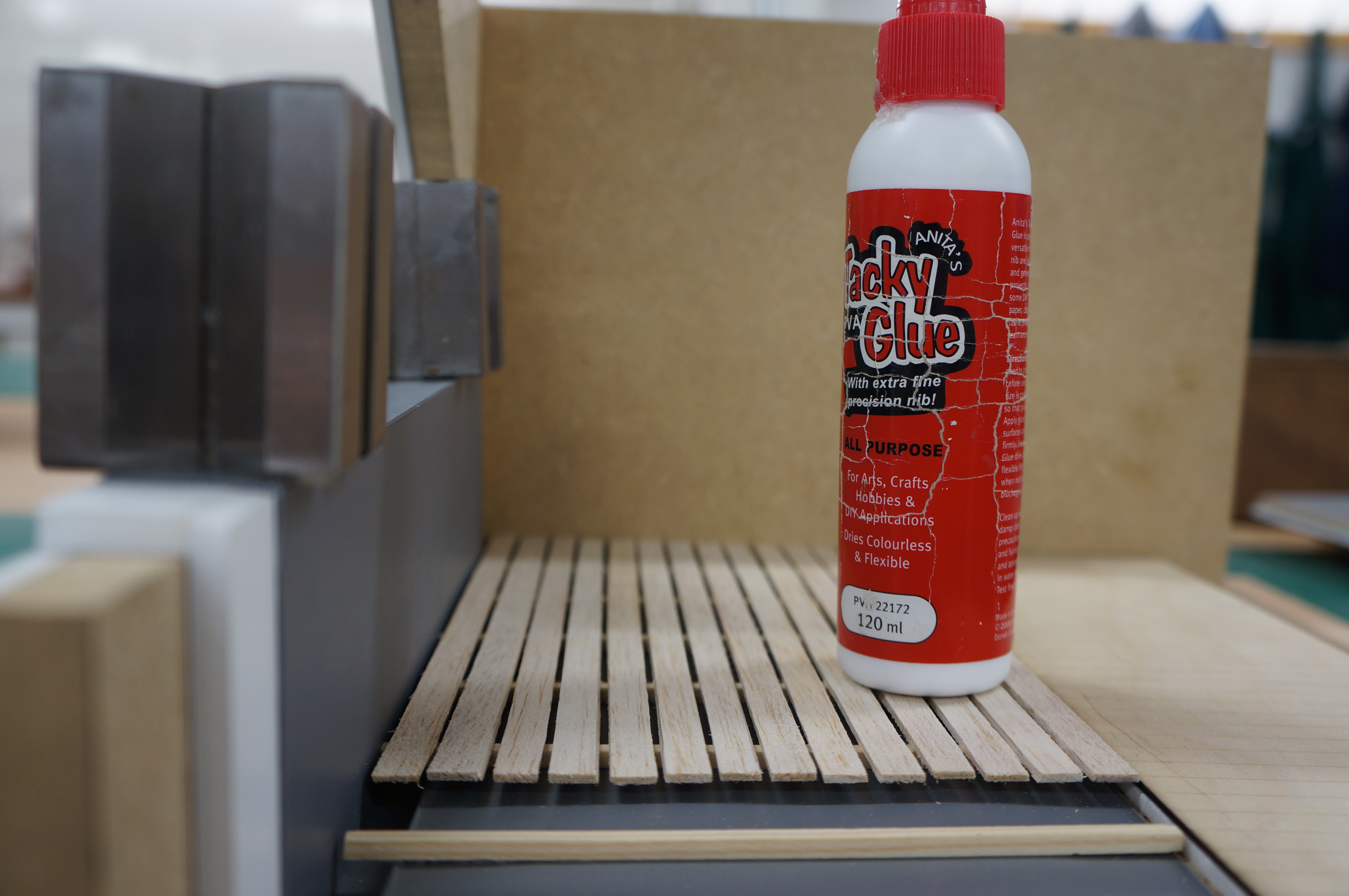
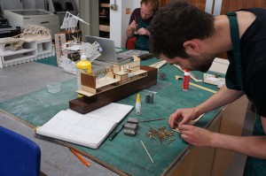
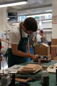
5th Year MA student Daniel Kempski came to the workshop fairly late on in his project with a need to convey multiple aspects of his design proposals through model making. Having successfully completed his two projects and some valuble lessons learnt. Of particular note was the time consuming engraving and cutting of the cork elements. The results of this were fantastic but it should be noted that this can be very time consuming and therefore potentially costly in terms of laser cutting time. We asked if Daniel would write us a piece to accompany some images of his models – he responded in great detail!

We look forward to seeing some more of Daniels projects next year.

The full description of the project and the application of the models made with us is explained here:

“The culture of use:reuse within the construction industry is an emerging area of importance within the field – with firms being placed under increasing scrutiny to change their methods building demolition and deconstruction in order to evolve to meet the growing demands of waste management. It is key to address this issue parallel to the growing dereliction within our cities – with many buildings being demolished once being deemed unusable.

How this can be linked to programme arrives through the notion of an Urban Auction House: a place where individuals can bring their waste materials (arriving as deconstructed elements) and then be further sold to buyers who can make use of these products.

The scheme acts as a hub for all types of individuals within the construction industry. It tries to establish an even playing field for its users, with products being available at a reduced price due to their imperfect nature – enabling the customer to be able to purchase construction materials at a cheaper rate, seeking to reduce the current gap between small and large scale developers within the market.

The aim of the design is to maximise retention of the existing building (Albert Warehouse), while not constraining myself to remain within the existing structures parameters and potentially harming the programmatic outputs. I aimed to change and manipulate these aspects of the existing form that I felt did not fulfil its true architectural potential.

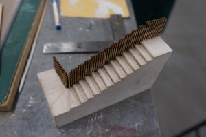
An entire new central bay is established between two existing segments of the build – enabling a more focused entrance point to be generated – recessed back from the roadside, with an element of grandeur created through the staggered, vaulted stonework.

1.100 model (10)

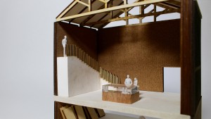
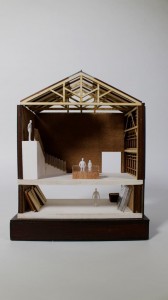
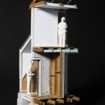
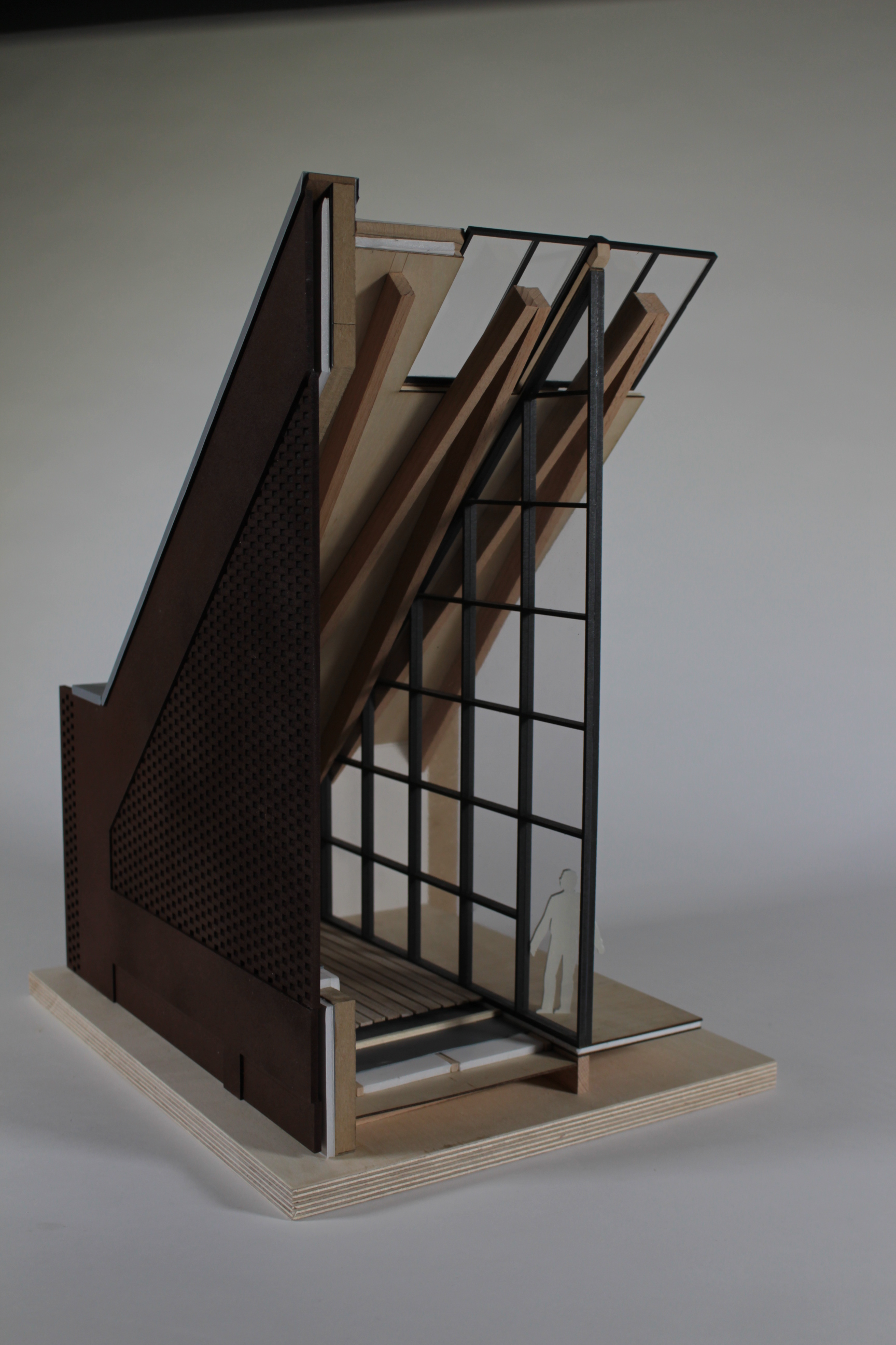
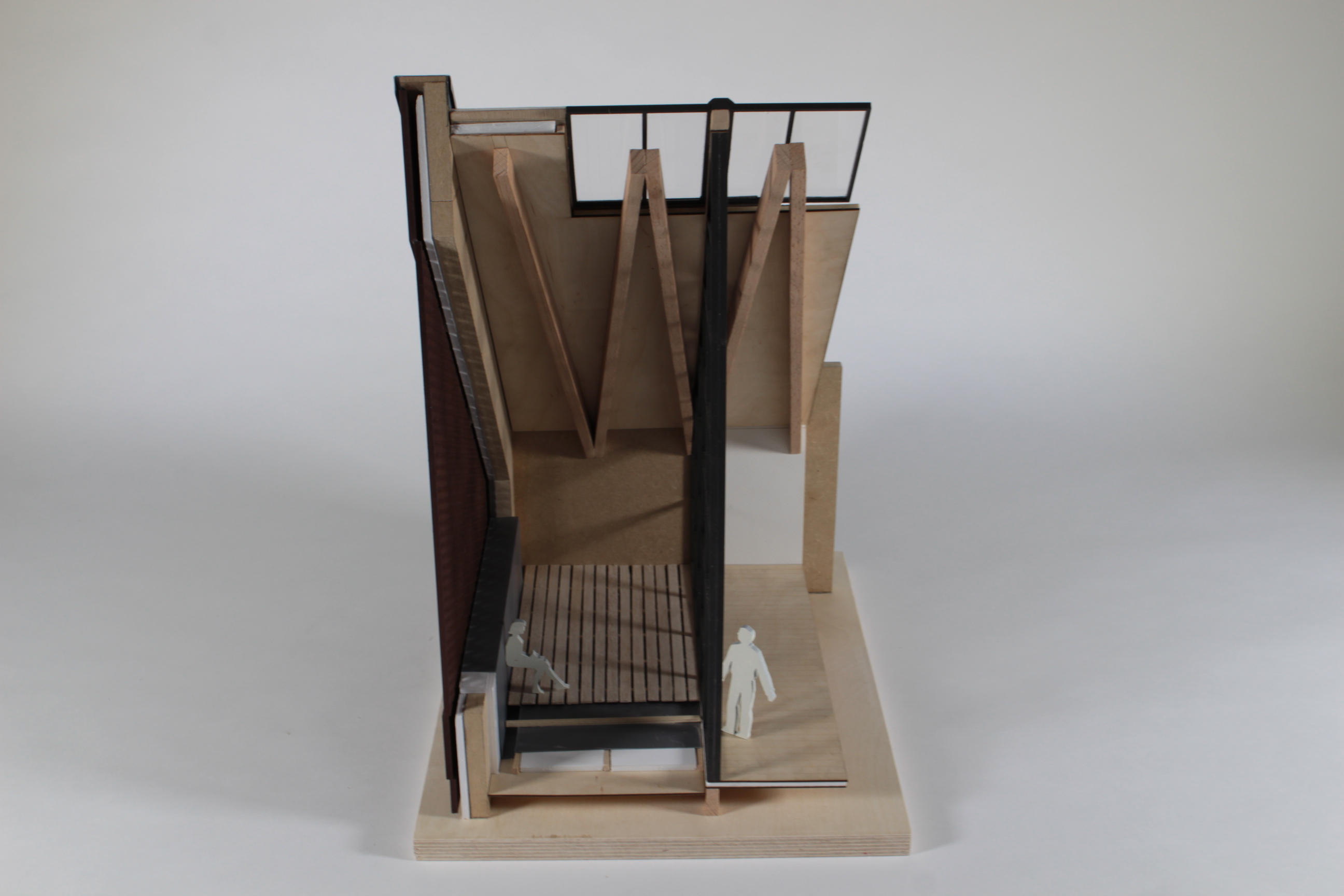
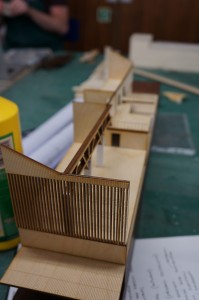
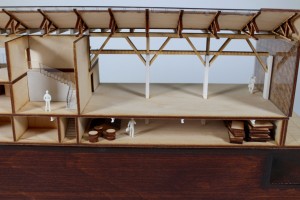
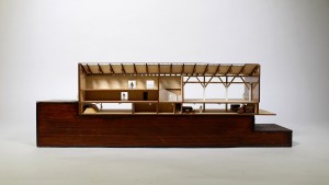
I feel it was key to investigate the building in two different scale models: a 1:100 Section through the scheme in order to understand the internal workings programmatically; and a 1:50 Bay Study to investigate the materiality and light qualities.

1:100 Model

One of the more demanding changes to the existing structure arrives in the form of the central bay being deconstructed and replaced by a primary structure primarily formed by reclaimed stonework sourced from Quay House (one of the four Urban Mines). It was vital to interject a new, more accessible entrance to the building for the main visitors entrance in order to establish a focal point for the east facade (for sake of both functionality and aesthetics).

Recessing the entrance away from the pavement provides a much needed forecourt, reinforcing this new change of threshold through vaulted stonework encapsulating the individual as they proceed to enter the Auction House.

1.100 model (11)

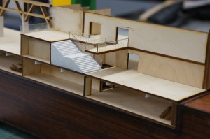
The Auction Hall is embodied within a double-height space, overlooking the River Irwell – creating the sense of theatre to be instilled upon the individual, with grand, exposed structure and a resonating acoustic acting as key protagonists. A raised platform further enables individuals to spectate during the auctions.

In contrast, the Lower Ground Floor functions as a back-of-house storage and preparation area. The workers gather and move the materials during their journey within the Auction House.
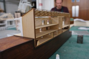
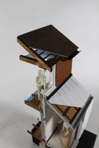
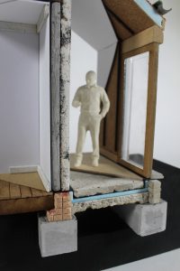
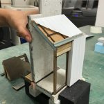
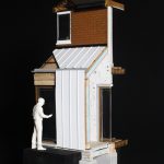
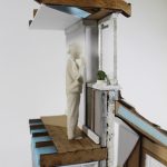
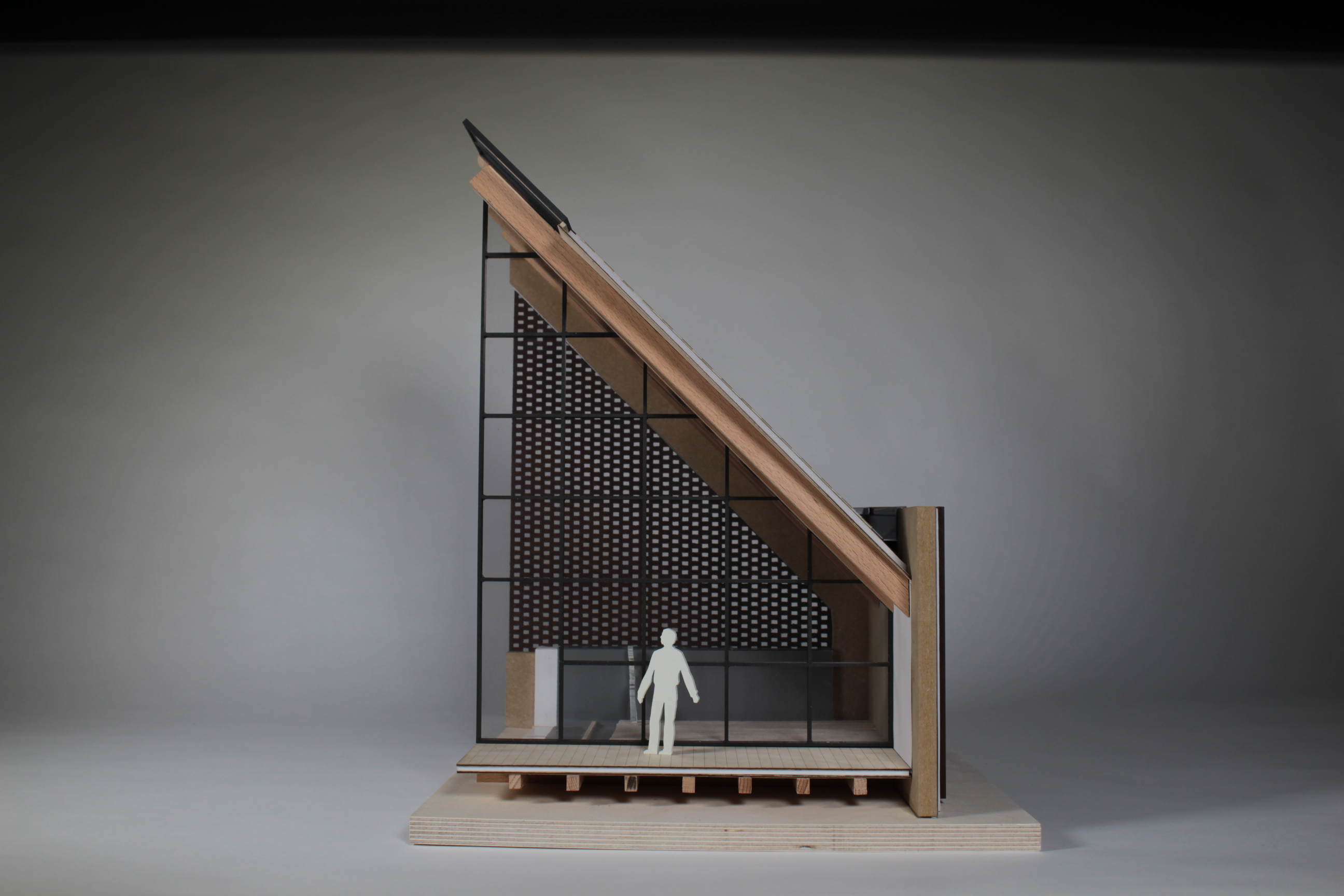
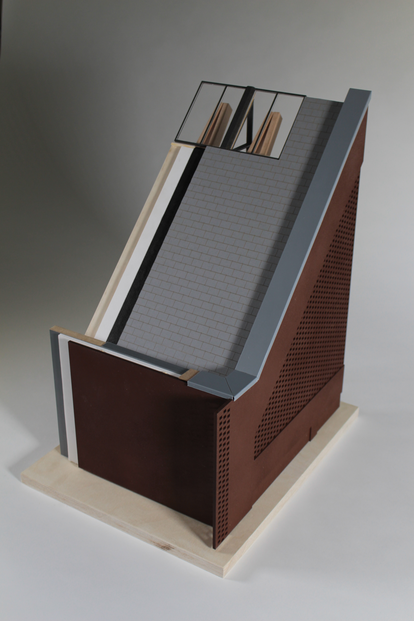
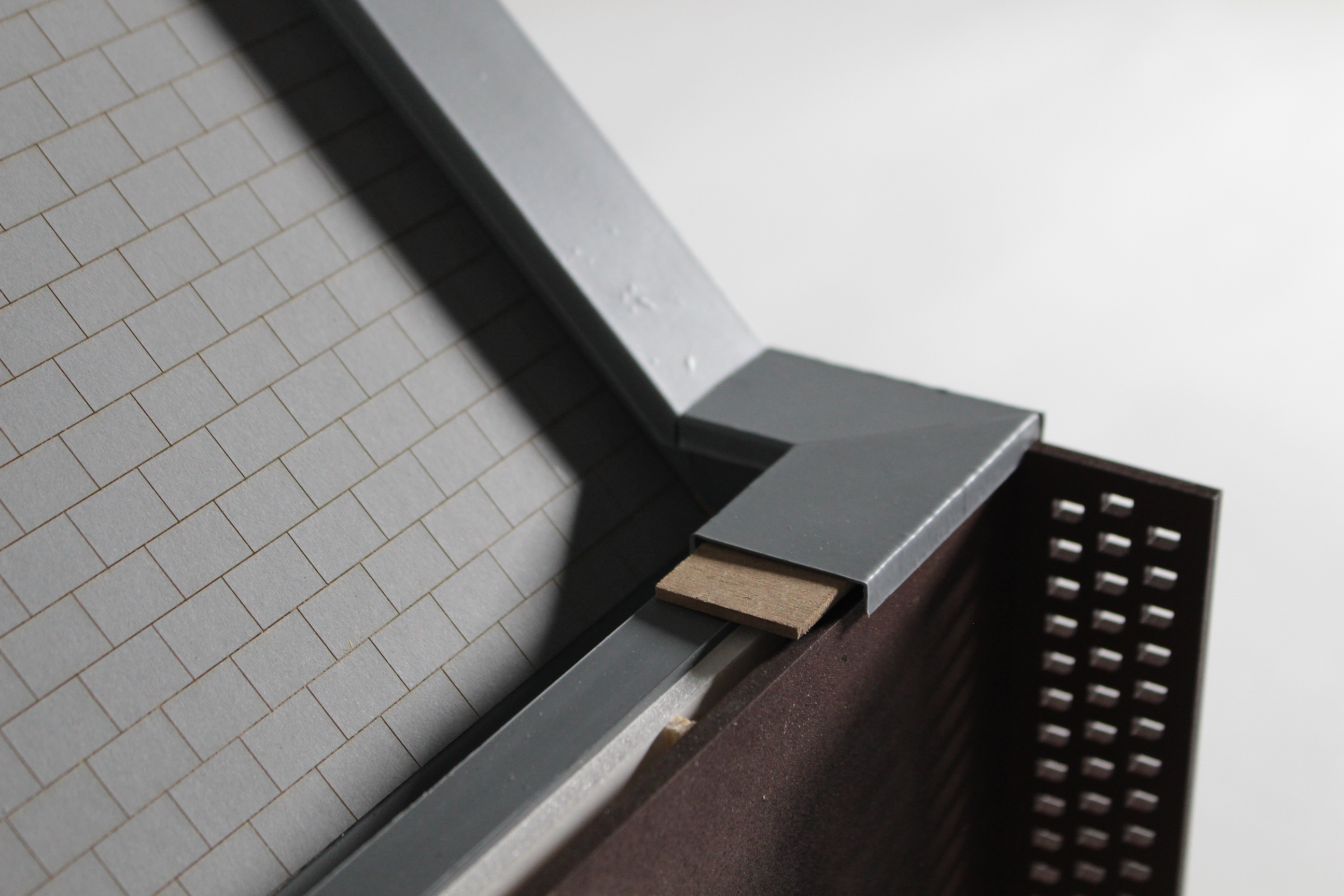
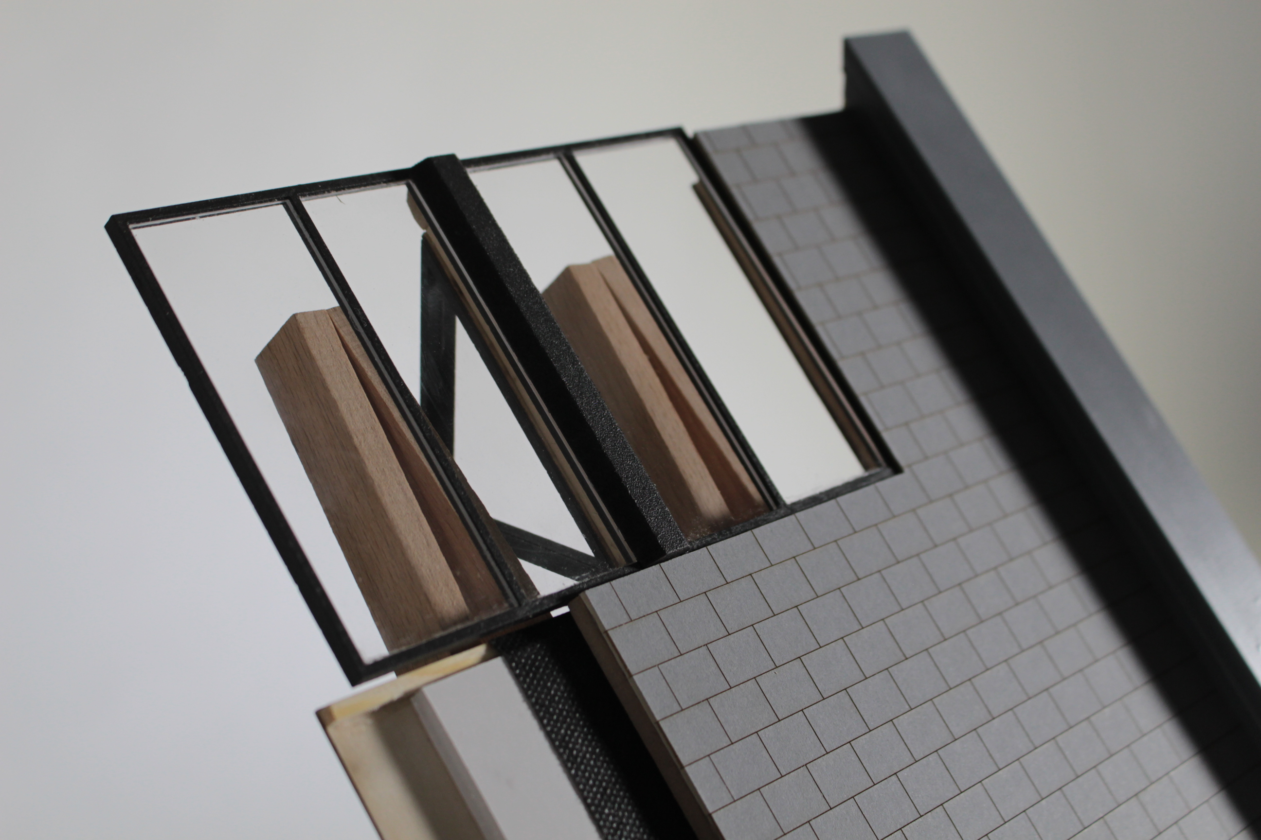
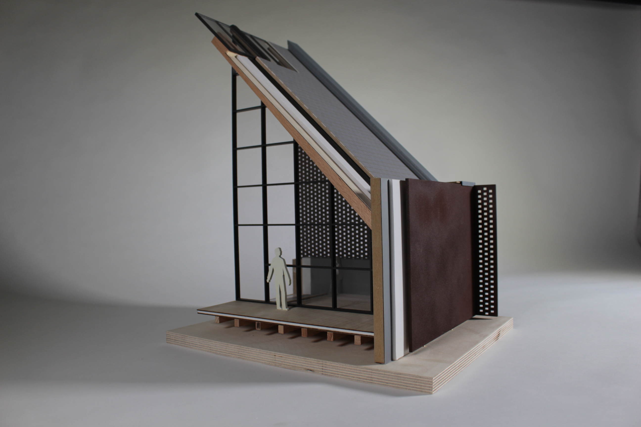
1.100 model (15)

1:50 Model

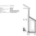
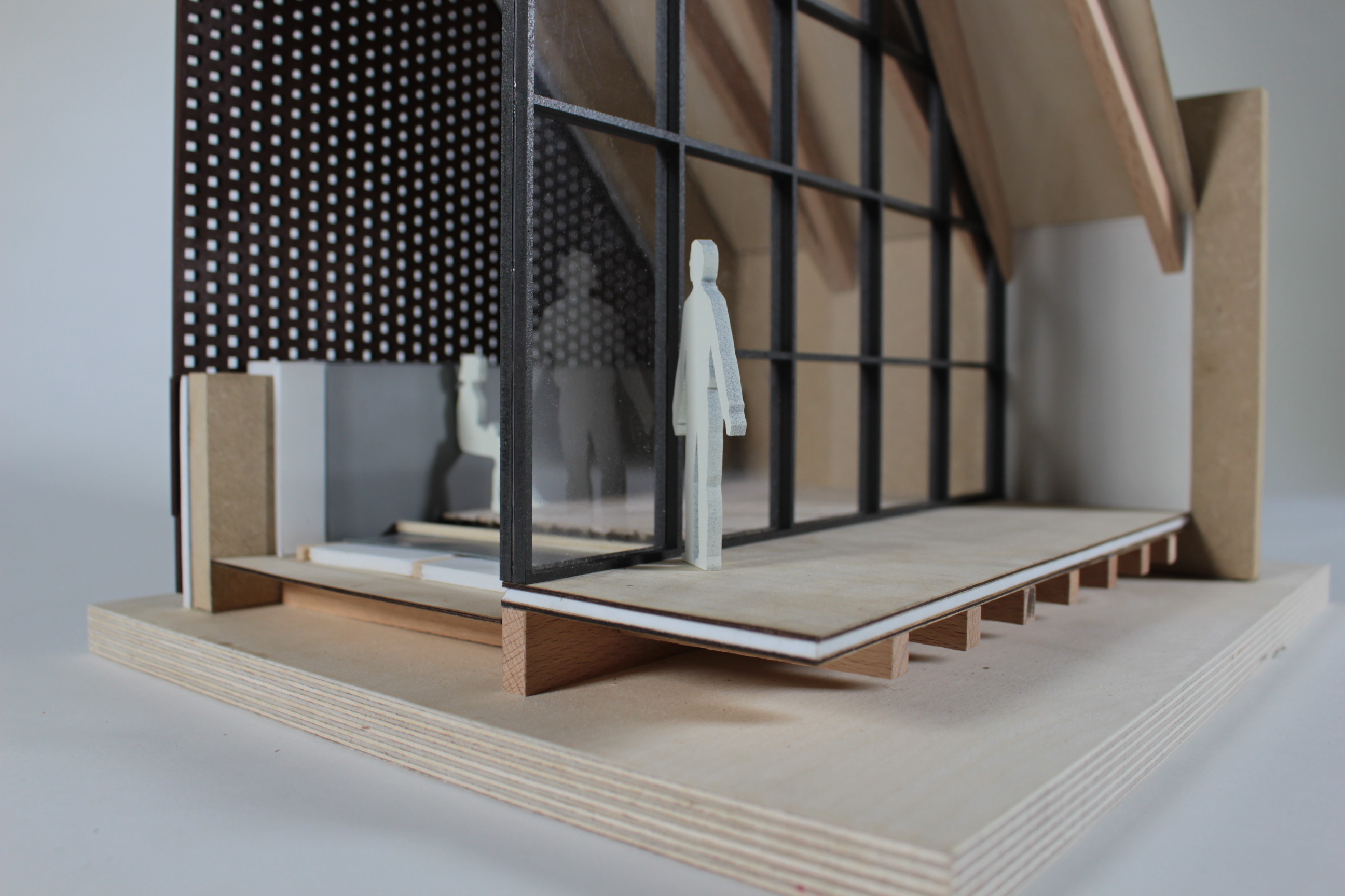
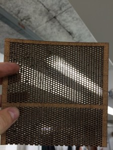
In order to gain a practical understanding of the atmosphere generated by the materials reprogrammed into southern elevation’s perforated brickwork facade,a scaled 1:50 model was constructed. The aim of the model was to investigate the internal light qualities predominantly, to ensure that the transitional space could not be deemed unwelcoming.

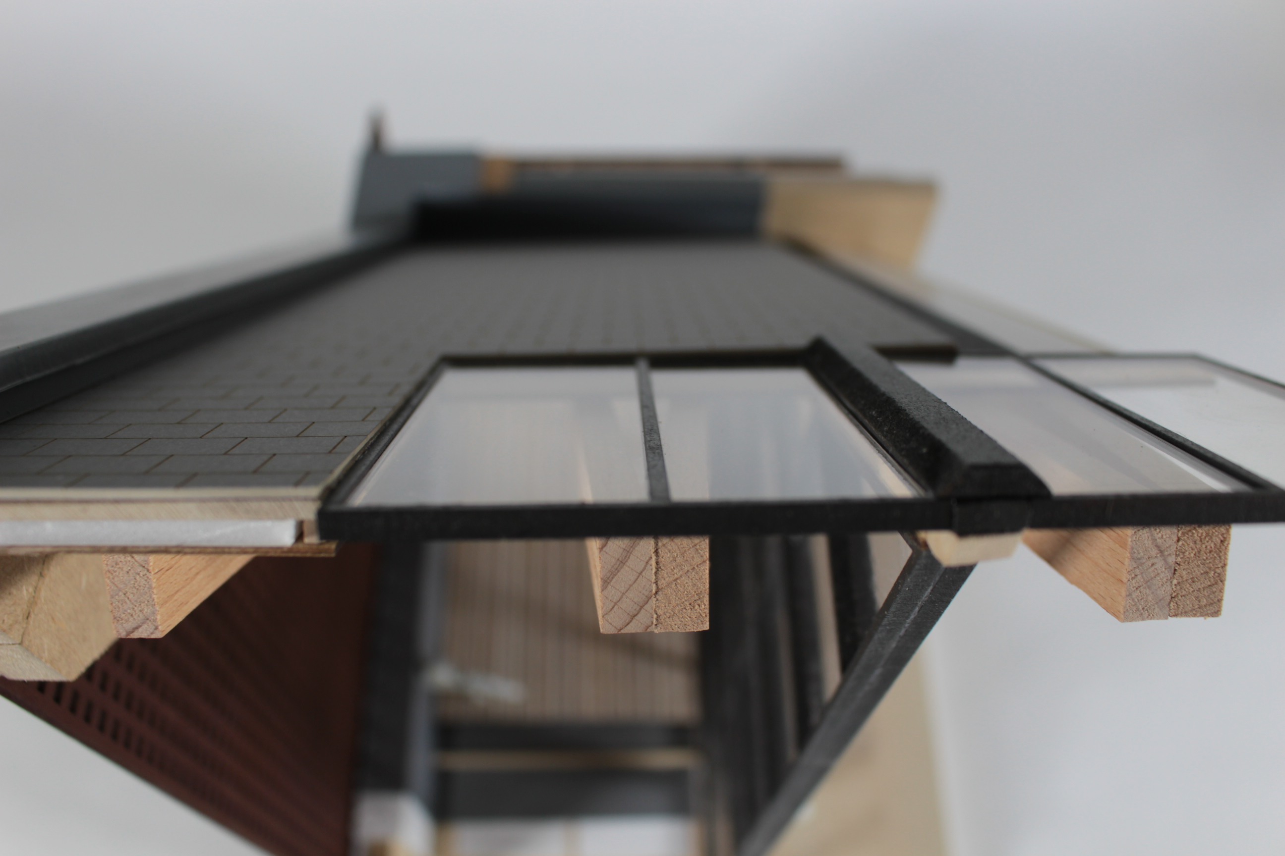
The model was also generated to create a built example of a key bay detail that repeats several times along that facade. The proportion between punctured brickwork and the actual structural masonry is key to enable the maximum introduction of natural light, while retaining structural integrity. The light qualities within the transitional spaces are key towards ensuring the success of the internal programme of the building – circulation spaces are there to offer relief in order to create a sense of separation between the Auction House and Galleries.

The large, double height spaces allow natural light to arrive from both the VSCs and punctured brick facade, allowing the central exhibition pieces to have their qualities maximised, as well as the space itself.
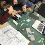
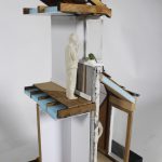
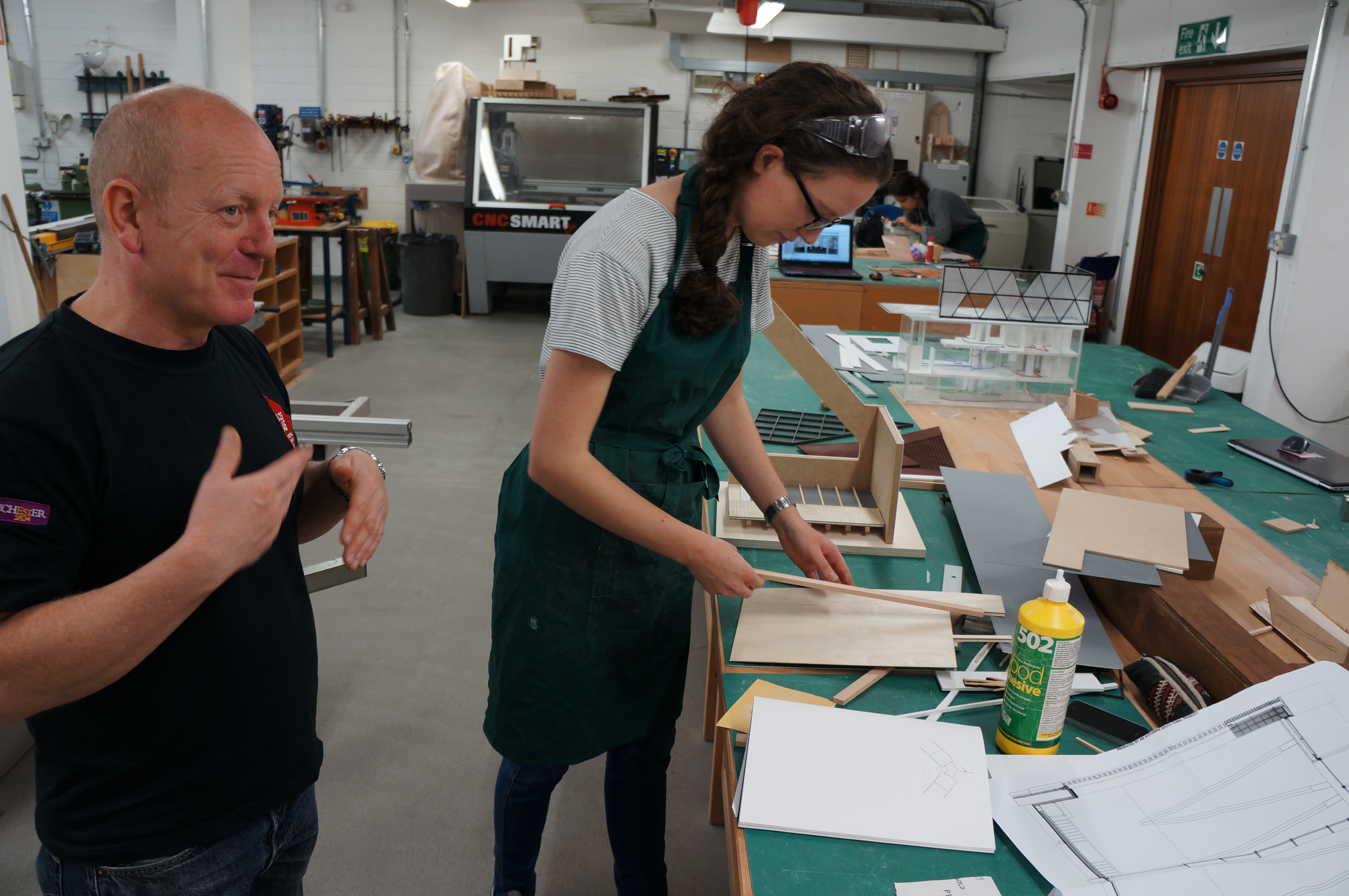
1.50 model (5)

Making the Models

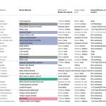
It was key to establish distinguishing characteristics between each of the materials used, as the scheme revolves purely around material reclamation (both architecturally and programmatically) It was vital to represent materials under same semantic in the building specification, as the same material choice in the model – enabling an easy understanding of the intended material discourse: e.g. obvious differentiation between stonework, timber, masonry, etc.

I felt it was key not to oversaturate the models with materials, instead working with three or four strong materials that work complementary to each other provided end products that felt cohesive.

1.100 model (9)

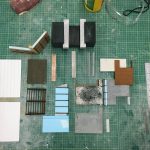
Within the 1:100 sectional model it was key to establish a strong juxtaposition of materials in order to depict what elements of the build are retained and newly interjected. This is attempted by utilising 3D printed elements to narrate the qualities of the proposed stonework bay, with the etched 3mm plywood representing part of the retained masonry bay.

1.100 model dan kempski (18)1.100 model dan kempski (12)1.100 model dan kempski (1)1.50 model (4)

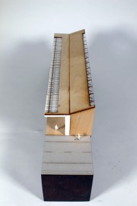
For the 1:50 bay study, 3mm cork board was used as the primary component to replicate the texture and ultimate aesthetic of the masonry – this was to ensure that minimal finishes had to be applied to the already delicate nature of the perforation post-cutting, providing the facade with a more natural demeanour.

1.50 model dan kempski (9)

DSC04456

Plaster-casts were made in order to distinguish a level of material separation within the space – focusing primarily between what is stonework and what is masonry. Both materials are reused, as recognised within the programme of the build, and thus is was key to attempt to create a more textured, used finish – achieved by placing a larger build-up of petroleum jelly within the moulds, creating a more textured finish.

Through the process of making both of these models, I feel that a greater understanding has been generated towards the atmosphere created within a building through the interrelationship of materials used within. It is far too easy to remain focused upon the external qualities of a site – and have that overshadow the internal conditions.

Combining both digital fabrication and hand crafted elements provides the ability to work efficiently and precisely, without generating a too-clean portrayal of the scheme. Regardless of the desired atmosphere within the build, I feel it is key to always develop your model-making understanding and techniques; with many components that could be made incredibly easily by hand, are now subject to digital methods due to sake of ease.”

1.50 model dan kempski (12)

1.50 model dan kempski (11)

‘Wood Street Mission’ 1:20 Section Model by Katie Williams

DSC04382

Year 6 MArch student Katie Williams wrote about her final major modelmaking project for us:


“The project is an extension to the existing building of the ‘Wood Street Mission’ charity, near Spinningfields. Due to it being an extension in a constrained site, the design had to respond to the existing ornate Victorian building, as well as create spaces for the existing and new programmes (and users) to connect. The extension aims to reflect and reinterpret the structural strategy of the existing building by using brickwork detailing on the facade, and a glulam frame internally to support floors and the roofs. Key details include recessed imprinted brickwork on the facade, large perforated brick openings and angled roof support beams. This 1:20 model is a section through a covered terrace area on the top floor of the four storey building. This space was chosen as it incorporates the key design details, as well as showing the terrace floor build-up, the internal floor, curtain glazing wall, the roof build-up and the parapet detail.
Where possible, materials were chosen that are a true representation of the actual construction. The glulam roof beams are cut from hardwood, and the internal roof finish is birch ply. Due to the angles involved in the roof, wood was easy to model with as it could be sanded and shaped. Most of the floor build-up was also done using realistic materials, such as foam board for insulation, and Styrene plastic for the waterproof membrane. The roof build-up is less accurate in terms of showing battens an cross-battens under the tiles, but the waterproof membrane is the actual tape used in construction. The brickwork facade and primary structural blockwork are represented in MDF. The facade brickwork was laser cut to show perforations and spray-painted in brown. The parapet cover is vacuum-formed grey Styrene plastic, which was then cut to fit over and around the top of the walls.
DSC04386
The construction of the model helped me to realise the construction issues that were not apparent in a 1:20 section drawing, for example the continuation of insulation on the inside of the terrace area.
DSC04397
When modelling the angled roof beams and working out the angles they should be sanded, it helped me understand the connections that I had previously struggled to model digitally. This was my first time using spray paint finishes and it makes a great difference to finish off laser-cut wood nicely.
On reflection, I can appreciate that in order to achieve the level of finish I am now happy with, the (whole) day spent planning the model was key.
If you fail to plan you plan to fail!
IMG_0246

This project is successful as it carefully balances necessary detail with material choices. The scale of 1:20 is perfect given the amount of layered detail Katie chose to show in her construction and the choice of this corner section was well considered as it shows a good selection of details and finishes that would expand throughout her whole design but are not necessarily required in their entirety to understand their application.

The success of this project is largely down to planning and material awareness. Rather than making the medium her binding constraint and only working around a particular tool, Katie rightly chose to dissect her model into components to help her understand its form as well as considering the most appropriate method of manufacture to represent each part.

It is clear is how well Katie understands the assembly of her building and the lessons learned in making this presentation model no doubt only strengthen that.

IMG_0248IMG_0250IMG_0251IMG_0252IMG_0265IMG_0269IMG_0273IMG_0279

1:100 ‘Performance Centre’ Cross Section Model by Philip Lam

Philip Lam explains to us how he used his model to convey his ideas for increased space and performance capacity:

Phil Lamm (1)

“On a site with limited space, my design tries to increase the audience capacity of a performance centre. The main space is found underground while the introduction of an outdoor space sits on top. The exterior space has been designed to respect and interact with its surrounding buildings.
The idea behind this model was to communicate and understand the spatial and structural qualities of my design.
As part of the brief, our tutors asked us to include a staircase and double volume room. By making a sectional model, it is possible for a viewer to see these components as well as help understand the use of space inside. Also by modelling a section cut, my buildings load bearing structure had to be modified to allow for missing components.

Phil Lamm (2) The material primarily used in my design is concrete. To mimic this in my model, I used laser cut MDF covered with spray painted sandpaper. Rather than making a mould and casting it, this was a quicker and more economical representation of the textural and structural qualities that were required. The half-arch was made using plywood blocks which were stuck together, cut and shaped using the band saw and bobbin sander. The grain in the plywood helped replicate brick and mortar. For the seating, I needed a material which is thin, yet strong enough to sit on the wooden support frames and decided on using mount board. Finally, I used laser cut frosted acrylic pieces to represent the translucent cladding found in my design.

Phil Lamm (3)

By making this model, I have gained further experience working with new materials, tools and techniques. I have realised that using the laser cutter is a fast and precise way to cut materials, but it can also slow you down if there are errors in measurements and tolerance. Careful planning before starting is essential. I really enjoy the process of constructing a good considered model and it is invaluable in further helping evaluate my design.” 

IMG_8786

Philips project pays attention to construction detail and his considerations with regard to material constraints and component accuracy come across well. It’s great to see turning points in project and there were several such points in this one. Philips model threw up issues such as floor levels and door placements that, once evident, were resolved through further making. We look forward to some more projects from Phil next year!

IMG_8791 IMG_8807 IMG_8812 IMG_8822

1:100 ‘Parasite’ Context Model by Anca Trimbaciu

This case study by Anca Trimbaciu shows us her proposed building within its enclosed site context of two existing buildings. So as not to take the focus away from her design the massing of the context buildings was kept simple. Anca wrote down her thoughts on the project for us:

“As part of first year’s final project we had to go the extra mile in explaining our design and idea. Therefore, we had to create a presentation quality model. My entire year revolved around butterflies, that being the animal I chose, so my building was also connected to them, being an indoor butterfly garden, a space for recreation and relaxation.

My design is a parasite building in between other two existing ones, which covers a very small space and puts focus around the staircase and the idea of ascension. As you move up you gradually discover spaces that are more open and luminous until the last floor which allows a panoramic view of Oxford Road from the inside of a “green utopia”.

Anca Trimbaciu (5)The model shows context, size and the purpose of my building. A section in the back of the model allows the viewer to see inside and observe how the building makes use of the adjacent existing buildings and how double volume appears during the ascension towards the top floor.

DSC04225

I used painted MDF for the adjacent buildings and the base of my model just to give an idea of their size and appearance, contrasting with my design through colour and texture. Other than that, the rest of my model is mostly made out of clear or grey acrylic as it was the best choice to either represent glass, metal or polished concrete. The triangular staircase is sustained by a wooden column which is covered in vegetation. Because the scale is only 1:100, I opted for showing ramps instead of creating each step out of acrylic.

DSC04227

During the making of this model I had my first attempt at using Autocad and laser cutting, and surprisingly, I succeeded. I learned how to spray paint in order to completely cover the texture of a material and I improved my skills in working with acrylic. I also got the chance to fully understand my building and its structure.

It has been two well spent weeks in the workshop and I am looking forward to my next project, even though starting a model might be scary at first, the results are most of the times really impressive and worth the time.”


Anca Trimbaciu (9)

The construction method for this model was well considered and, much like the building process of a 1:1 project, the order of assembly was orientated around the ‘core’ access, in this case stairs, providing support for the different levels.

Of particular merit here is the consideration to how the massing was created. Rather than being solid blocks, the context massing was made up by creating hollow boxes which were then coated with sanding sealer, sanded and painted. This method saves on material and overall weight of the model and can often be done for free with off-cut material.

Anca Trimbaciu (10) Anca Trimbaciu (13) Anca Trimbaciu (14) Anca Trimbaciu (18)

‘Peacock Museum’ 1:50 Cross Section Model by Mahishini Vasudevn

DSC04037

In another First Year case study we asked Mahishini Vasudevn to tell us about her recently completed project for the ‘Resolution’ brief:

“For our first project, habitat, I chose Peacock as my animal client so I made a design that would stand proudly and attract the eyes of the people just like the Peacock would do. To portray this, my design had a cantilevered floor which protrudes over the pavement of my site in Charles Street. The facade was designed to have stained glass which had the same colours as the peacock. In my design I have mainly focused on grasping the attention of people instantaneously.

In order to convey the most information about my design, I made a sectional model to give an insight to the structural aspects and the interior detailing of the design like the cantilevered stairs and the circulation around the building.

DSC04091

In the case of materials, for the glass facade I have used coloured acrylic as it best represents the colour and transparency that is implied in my design.  As for the columns, beams and floor joists I used Styrene H-columns which were sprayed in black to represent steel frames. The floors were made with MDF wood to replicate the wooden floors. The pathway with granite paving slabs was laser engraved on grey card to show the colour and the small amount of texture that I wanted to show. The interior was done with wood and acrylic. In my model I have tried my best to produce them in such a way that they almost represent the same materials that would be used in reality if it were to be built.

DSC04135

Through making this model I have learnt new techniques of model making. It has taught me more about my design like the structural connections and how a design comes together as I was able to have a 3D view of my design. I’ve learnt how to plan my work and handle time with care.

Model making has been the best experience I’ve had as a first year architecture student and I’ve enjoyed working in the workshop.”

IMG_8084 This model is put together with a good selection of materials that help to demonstrate the different component of the design shown in section. Mahishini made good use of pre existing strip materials by choosing styrene H beams to construct what would be the steel frame of her building if made at 1:1. Strip materials such as these are extremely useful in section modelling and we hope to stock a range in the near future. In the mean time they are available from 4D Modelshop where you can also register for a student discount quoting either myself or Jim as your tutor here at Manchester.

IMG_8152 IMG_8244

IMG_8088 IMG_8248 IMG_8250

‘Arch Game Lab’ 1:50 Cross Section Model by Estelle Xin Yun Ang

DSC04032

First Year Student Estelle Xin Yun Ang has just completed a 1:50 section model of her proposal for the re-purpose of vacant space under a railway arch way. Estelle kindly described her project for us:

“I chose to build a model in which part of the facade was removed to communicate the details of interior spaces and the assembly of structural components. The railway arch was modelled as a section to show how it acts as the ceiling of my design. I modelled the underground and made a window to give a good view into the basement. The facade detail was quite important in order for me to express the sense of gaming, which was why I took the time to paint the tiny offcuts.

DSC04082

The exterior spaces surrounding my design is extensively graffitied which inspired me to design a gaming studio where the potential of play is explored. I incorporated game buttons into the design of the facade to convey my idea of gaming.

DSC04092

To model the context, I decided to use plywood as the texture provides a good representation of the brickwork for the archway. For the ground/base, I used mdf wood and applied wood stain to give a good contrast to the light coloured arch. I spray painted the laser cut mdf in grey to show the concrete floor plates. For the walls I chose to use vac-formed styrene to achieve a permanent curved shape. I added strips of acrylic between the two pieces of styrene to make up the thickness of the wall and that helped save some material.

DSC04120 DSC04139


I overcame the difficulties of modelling the curved shape of my design and I have learned to use different techniques on different materials to achieve the best result. After a few trials and errors I was able to understand the construction of my design. This is what I find interesting because there are so many ways in making a model and through experimentation I get to know which method works best for my design.”

IMG_8220 IMG_8226 IMG_8228

What is clearly shown in this model is the attention to making each element correct for assembly. This patience and consideration is something we should all aspire to when designing and making. Often one of the hardest things to do during a project is accept that something you have made is incorrect and should therefore be re-made. Whilst this may seem like wasted time it is exactly the opposite and by taking a step back from the project to look at what you have learned you will see that such mistakes are necessary for your own understanding of the design as well as gaining a better understanding of material and machine constraints when making.

We hope to see more projects with this level of thought and consideration in the coming weeks leading up to the final submissions and in future first years.

IMG_8259 IMG_8262

1st Year History of Architecture Paradigms Project

We’ve had a busy few weeks in B.15 with the last week and half dominated by this first year project.

In conjunction with a series of paradigms lectures first year students have been asked to choose a piece of historically significant architecture to replicate and study through multiple means. One of the requirements of this brief has been to produce a section model allowing the observer to view the construction framework and internal layout of the building they are looking at.

1st year paradigms 2015 (6)

1st year paradigms 2015 (1) 1st year paradigms 2015 (7)1st year paradigms 2015 (10)

The results from this have been very good with groups taking time to consider different aspects of the real constructions and how they might best be represented at scale and within the time frame allowed to produce the model. Materiality was a prime consideration with the most successful examples providing a balance of different materials across the model construction.

1st year paradigms 2015 (8)1st year paradigms 2015 (22) 1st year paradigms 2015 (9) 1st year paradigms 2015 (11)

Things to Consider: Always Printing Plans

One crucial part of getting these projects started was to get correctly scaled plans printed for reference. A number of groups hadn’t considered this necessary as they had smaller plans and scale rules for conversion. We highly recommend getting at least one printed correctly scaled site plan for reference when producing your models. Without one to hand you will spend a great deal of time referring to cad or wrongly scaled drawings for reference when you could easily be comparing your model components to an accurate plan on your desk .

1st year paradigms 2015 (12) 1st year paradigms 2015 (13)

Photographing Models

As part of submissions students also had to produce a pamphlet detailing the key facts about their chosen piece of architecture. This meant taking photographs for their models had a duel use providing images for their pamphlet and their portfolios. Anyone wishing to use the studio space to take photos of their current or past work should drop in and we can advise on availability and help you set up to shoot.

image3

1st year paradigms 2015 (14)

Stahl House 22 (9)Frank House (20)Frank House (27)The completed models were then placed together with the other submission requirements in a small exhibition of paradigm studies back at the studio space.

image1 image2

Some great work and valuable lessons learned for all – first years are really pushing the expectations for the next waves of students! Well done everyone – see you for the next project!

Scott and Jim

‘Retrofit’ Structural Study Model by Paul Thornber

Paul Thornber Structural Dteail (6)

MSA Praxis student Paul Thornber produced this ‘rough and ready’ sketch model in just 6 hours and cost him the grand total of £0! Made entirely from waste scraps this model clearly conveys the structural arrangement of Pauls project without need for expense or time consuming methods. More importantly the process of planning, marking out and making the model has been a learning experience as Paul describes below:

“I intend to use the model to explore how structural decisions affect spatial conditions.
The model was used to help make decisions, in the development stages, regarding structure through experimentation.I was able to economise on structure through building at scale and assembling the model by hand.It also helped me prove that I understood how the buildings structural strategy worked.

Paul Thornber Structural Dteail (10)

Through making this model I have learnt how to form and develop the plan of a building through a process of experimentation in both 2D and 3D.
Quickly switching from plan to section to model and back again helped me rapidly develop ideas that worked both on paper and in 3D.

Paul Thornber Structural Dteail (56)

This model gave me an insight into the next stage of model making for the final output of the next project. I will now know what works and what doesn’t before starting a more refined version of this model.”

Paul Thornber Structural Dteail (40) Paul Thornber Structural Dteail (23) Paul Thornber Structural Dteail (12)

This is how the medium of modelmaking should be used in my opinion. By employing making as a tool to develop your ideas you are opening up yourself to technical processes, material constraints and lessons that can be directly transferred to your design decisions when working at to 1:1 scale design.

You can see more of Pauls work here: http://www.paulthornber.com/

Scott