Anyone who has experimented with casting will appreciate that the process of designing and making the mould is the most critical part of the process. ‘One-off’ simple block or slab casts can often be produced using scrap mdf to create the framework before pouring and then breaking the frame for removal of the completed cast. This is usually successful but can be restrictive in terms of detailing and can often mean destroying the mould to remove the cast.
In order to capture more intricate details of an object we can use silicone rubber which is widely used in the art and design industry. The main drawback of using silicone is its cost and only having one-purpose once it has cured.
A great alternative we are encouraging for testing is ‘Gel-Flex’ PVC Compound which can be melted, poured, cast into and then remelted and re-purposed to make several moulds with the same amount of material.

 Using Gel-Flex
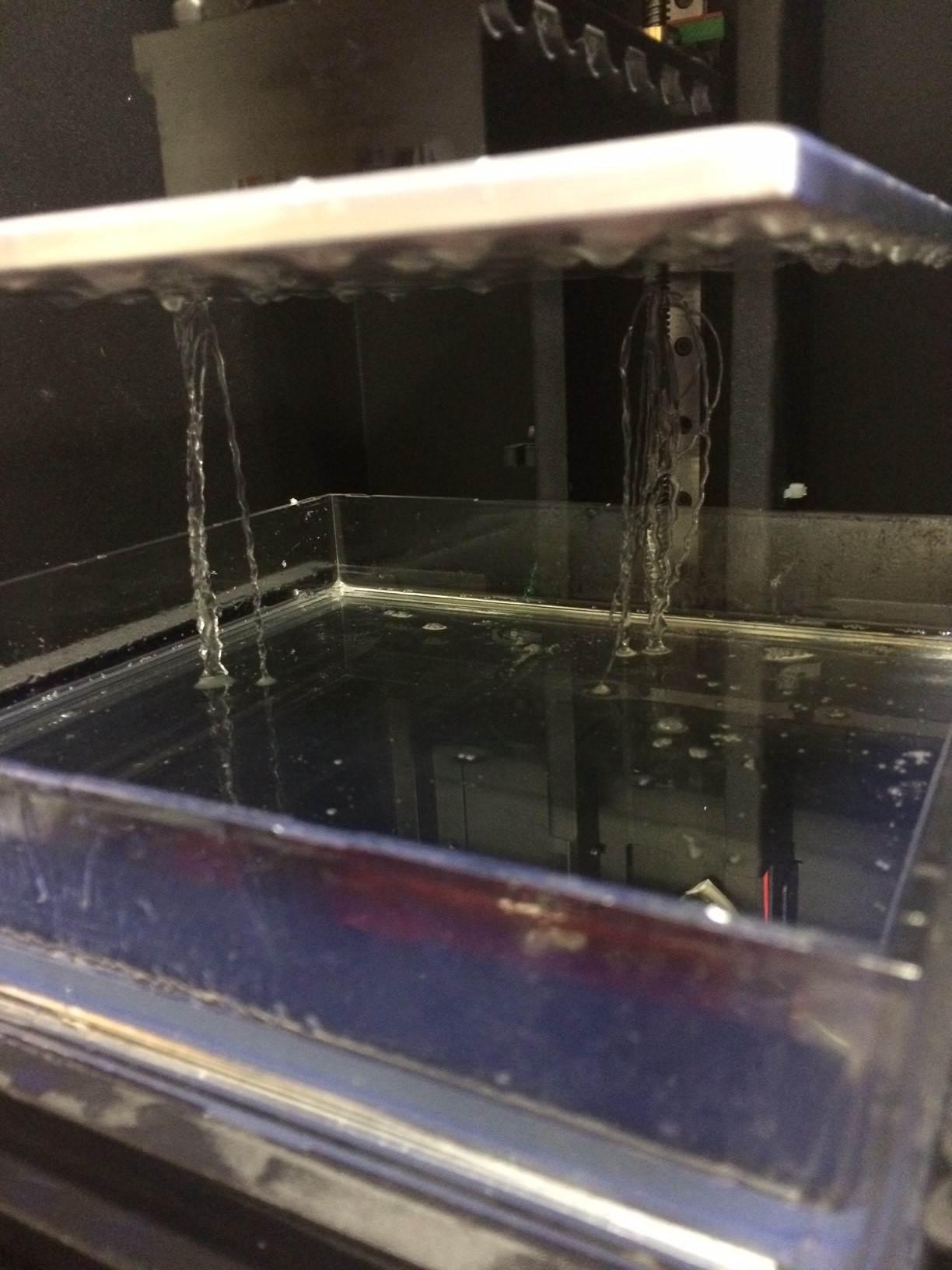
At present we are unable to provide a method of melting the compound in the workshop but this product can be easily used at home by heating using a conventional hob or microwaved in a suitable dish (As Monty explains below – preferably glass!). Instructions are provided with the product which you should always read and make sure you understand thoroughly before using.

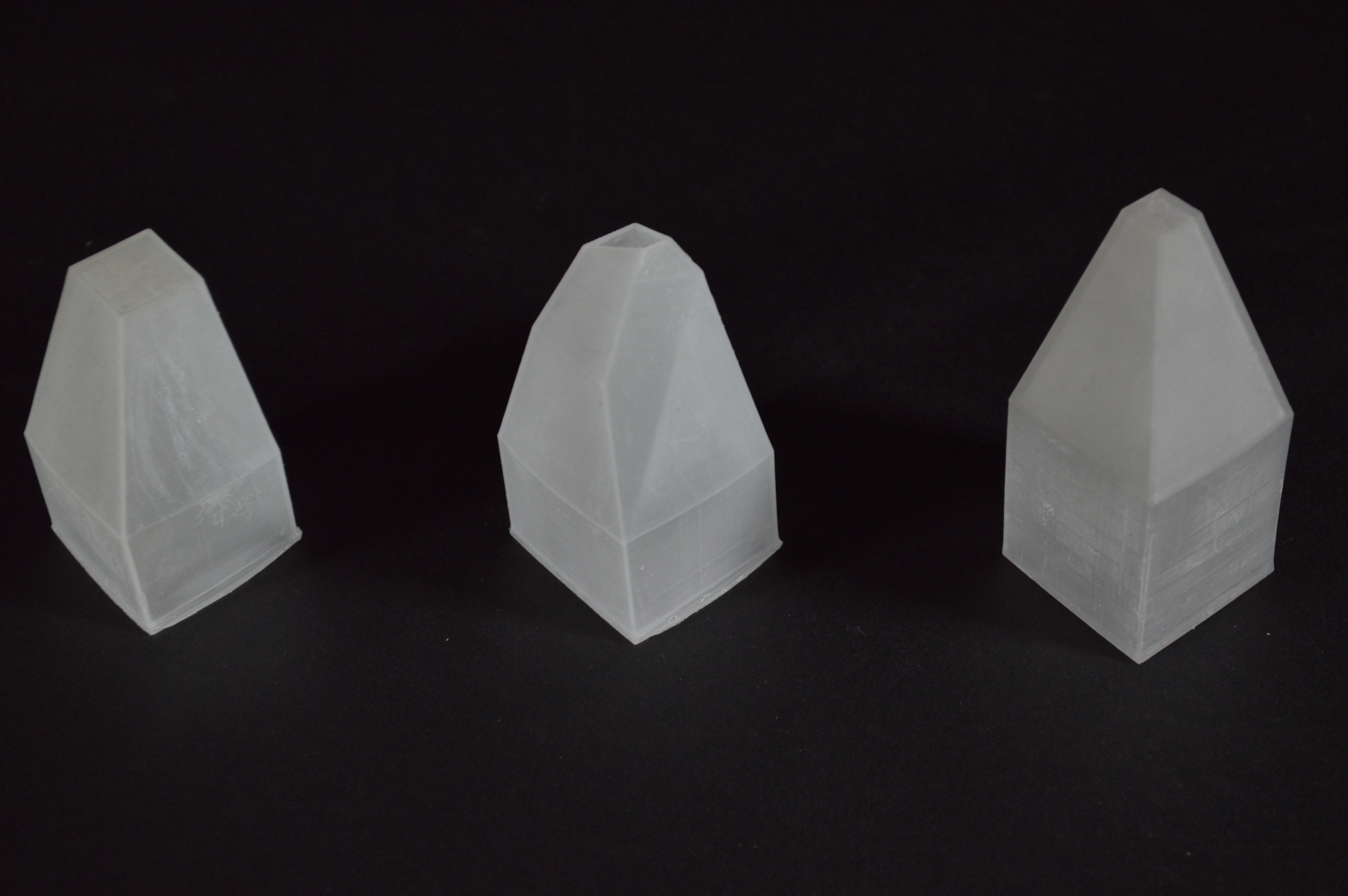
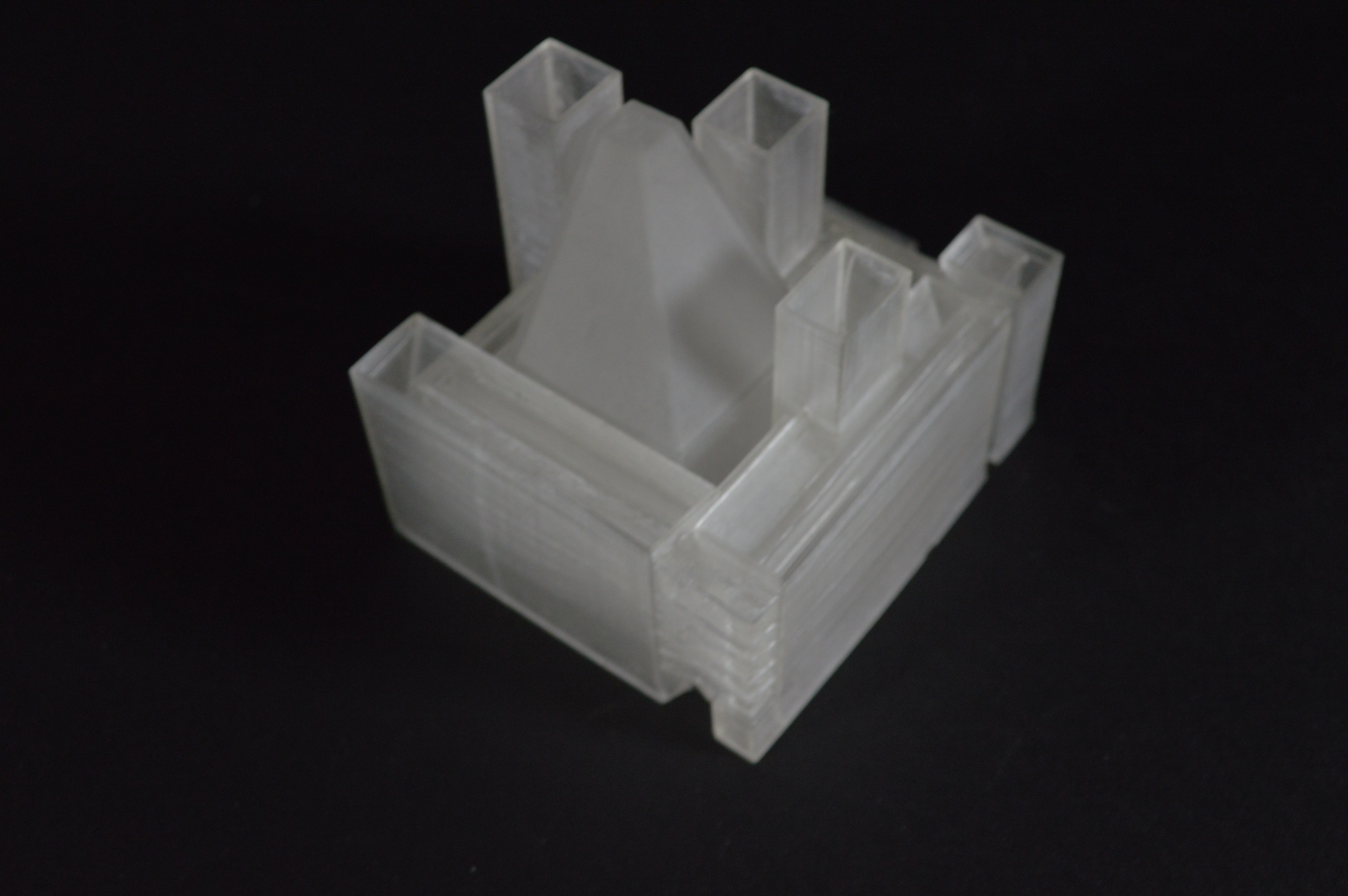
Once the product is in a liquid state it is poured in the same way as with conventional silicone mouldmaking into a box mould over the object you are wanting to cast.
The main drawback to using Gel-Flex is that it isn’t as durable when being used to produce high numbers of casts. Eventually the mould can become over-stretched and can rip. The beauty being that the material can then be melted again and poured to create the mould again – eco considerate and cost effective if you need to mould multiple items.

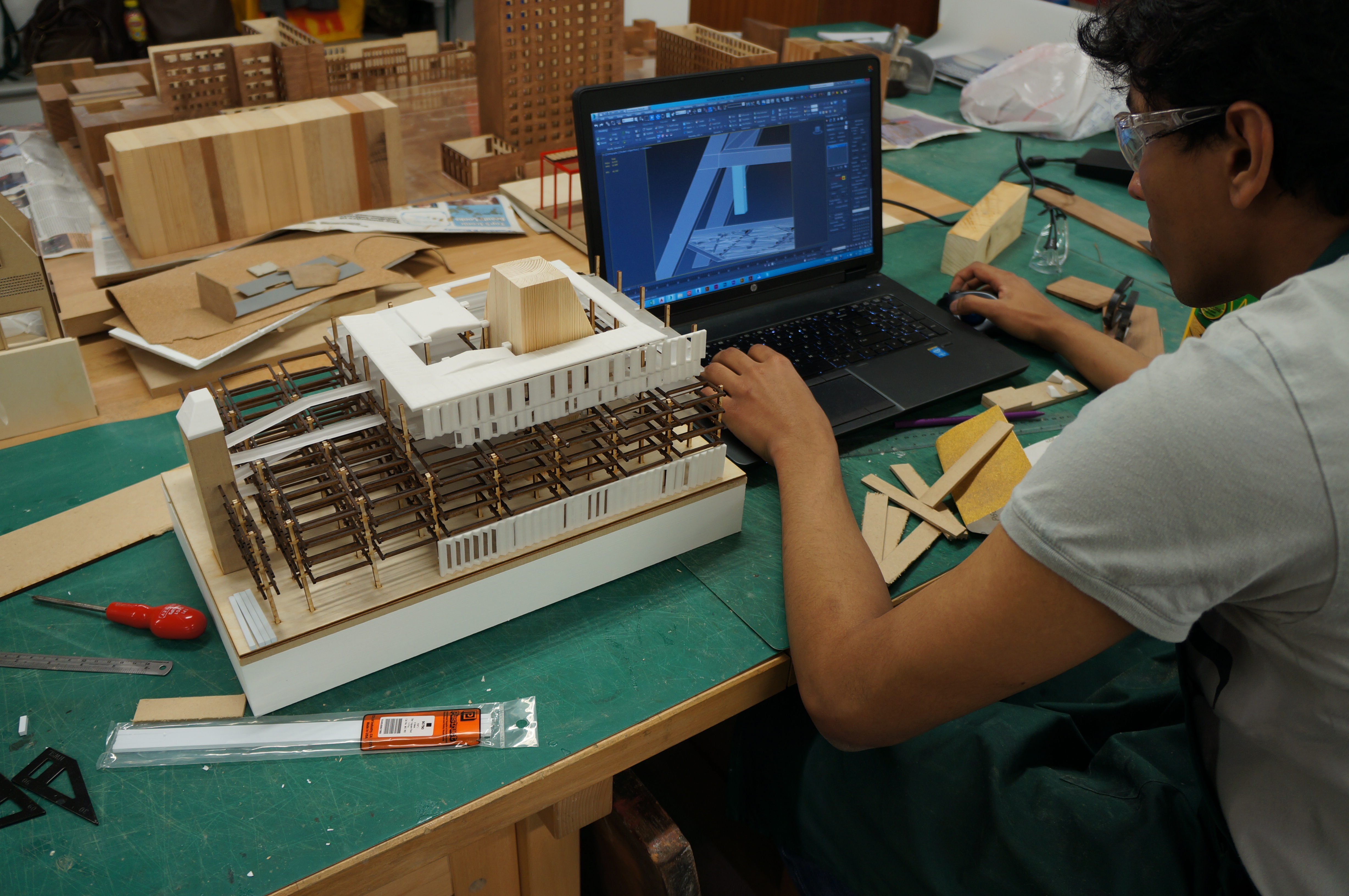
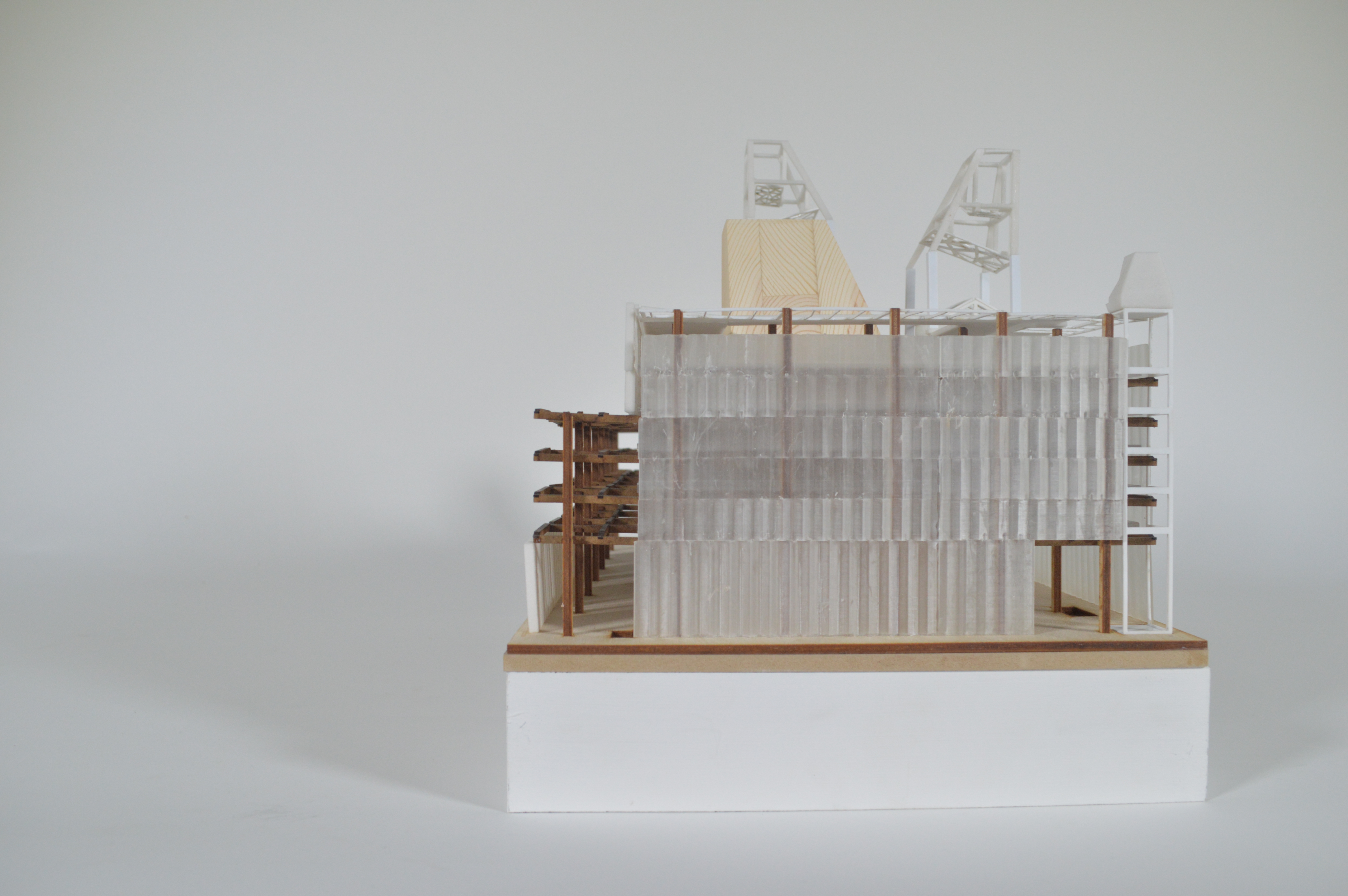
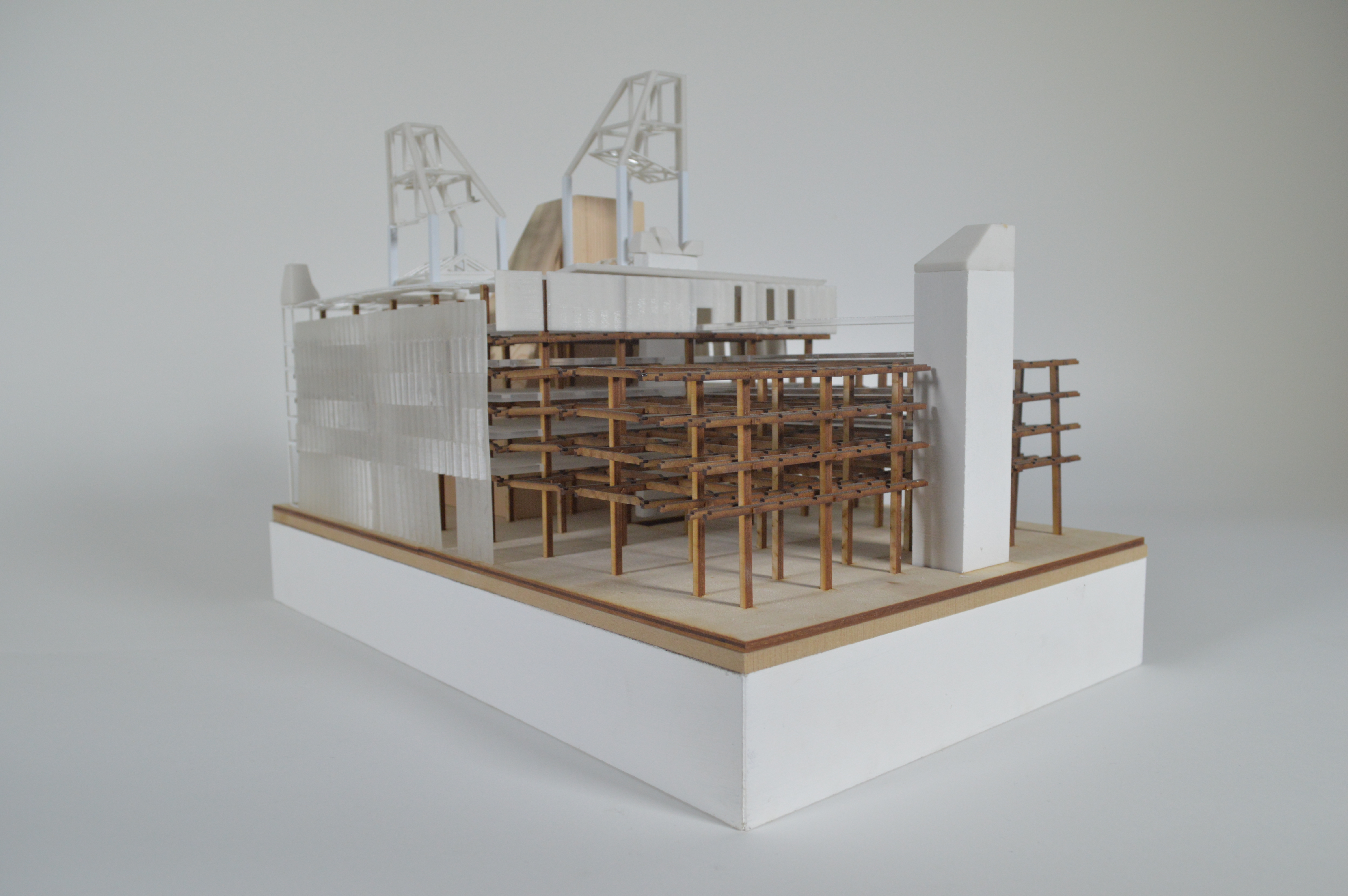
Case Study: 1:1 Facade study casts by Monty Dobney
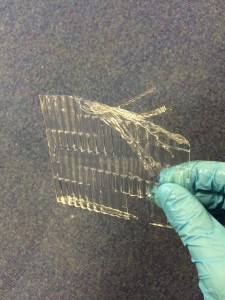
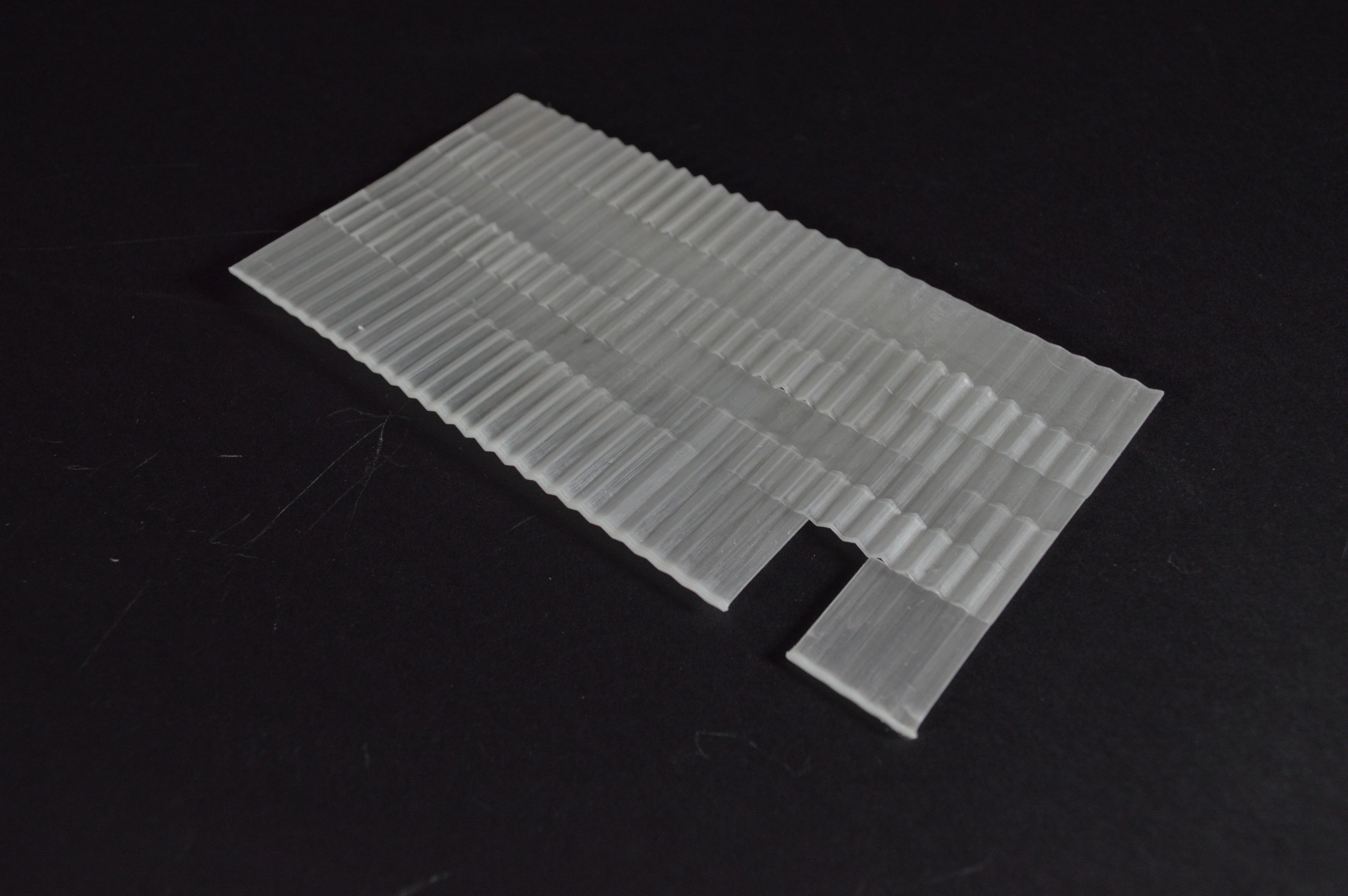
“Gel Flex was great to create the intricate detailing required to for a 1:1 model of my paternated bricks. I first laser cut and glued together (the most time consuming step) an mdf master for the mould to then be covered with the Gel Flex.
After reading the instructions I decided to melt it in a microwave oven, on the first attempt I melted the plastic ‘microwaveable’ container which I had decided to use to melt it in. But two containers stacked seemed to do the trick for holding their form! It was also important to keep checking on it as it can very easily ‘over cook’ which turns it brown (as can be seen in the image below) and a strong burning plastic smell! I successfully used the Gel Flex to cast from both plaster and wax.”


Gel Flex is available to buy from 4D Modelshop where you can get 10% student discount or at Fred Aldous in Manchester and can be found by clicking here.
 We are very pleased to announce a new modelmaking exhibition of student projects opening September 2016: ‘B.15: ARCHITYPES’