SLA Resin Printing by Akhil Mathew

It has been a year now since we purchased our own SLA resin 3D Printer. In this time we have had a varied degree of successes. Perhaps due to its relative infancy, we have come up against numerous issues with this printer meaning its use has been limited as it often required constant checking to ensure the process is working correctly. The best uses have come when a student has taken initiative to research the process for their own requirements. One such student is 3rd year Akhil Mathew who has kindly written about his application of the process and the various pro’s and con’s he experienced.

DSC05841

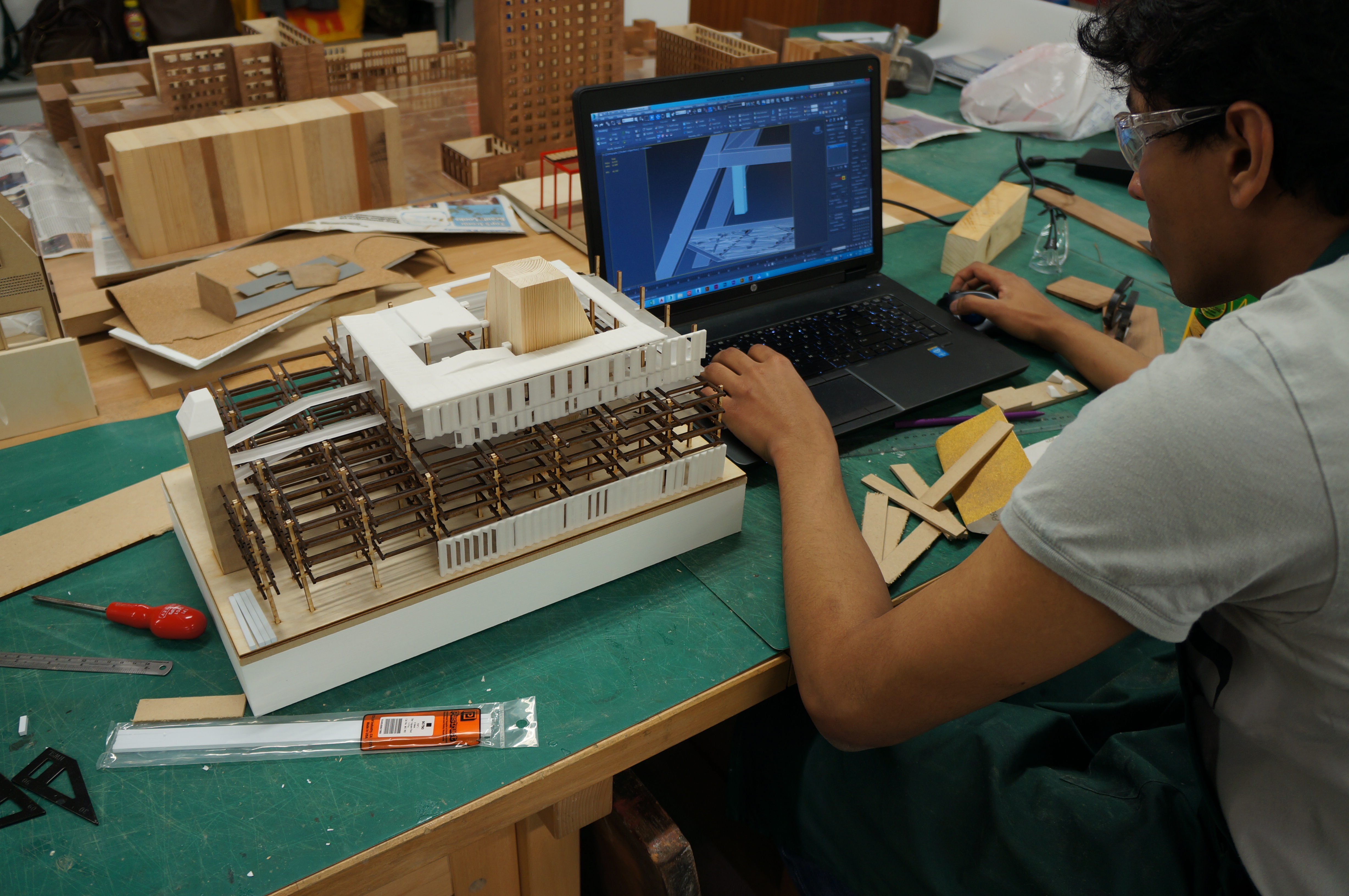
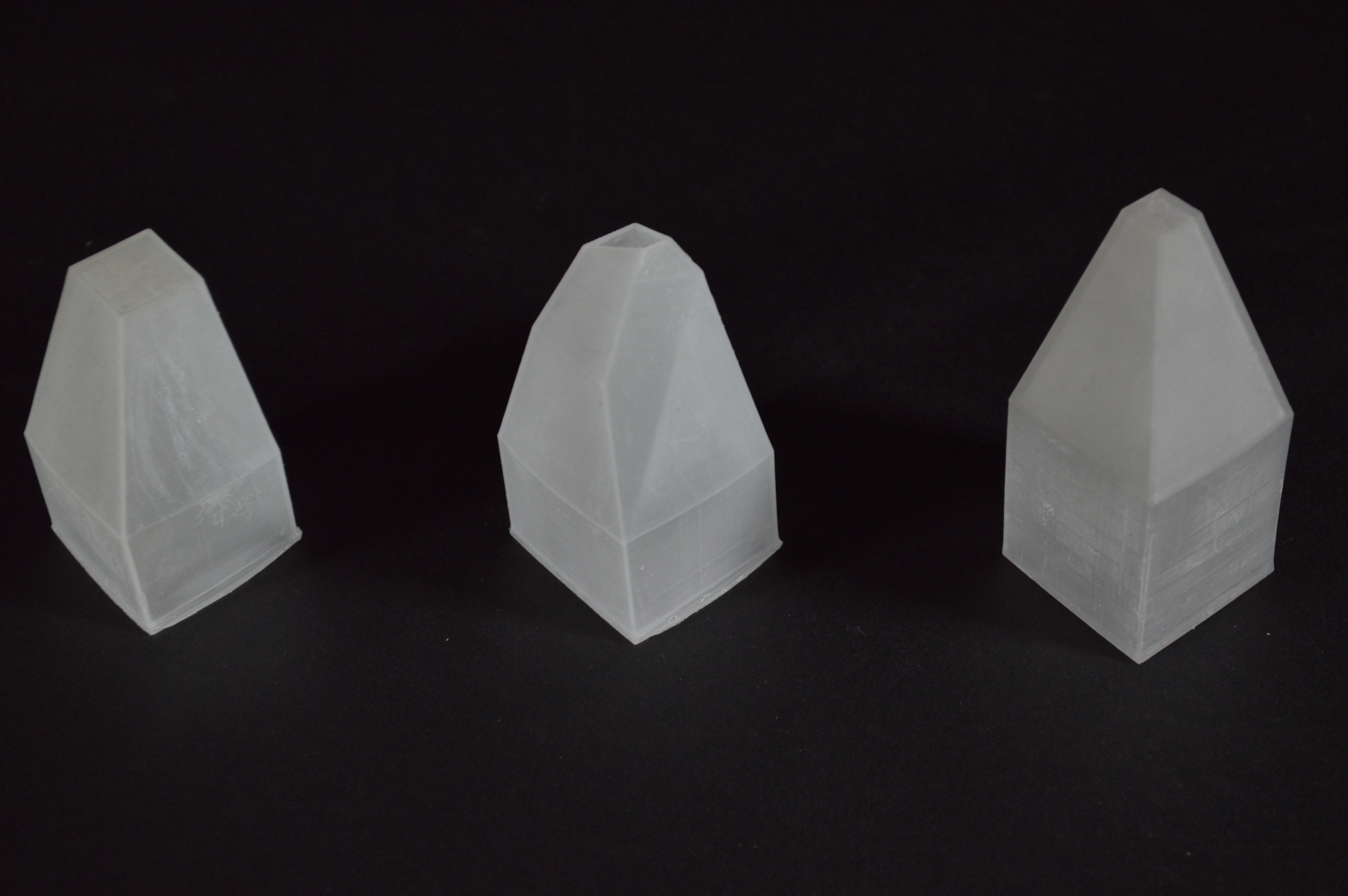
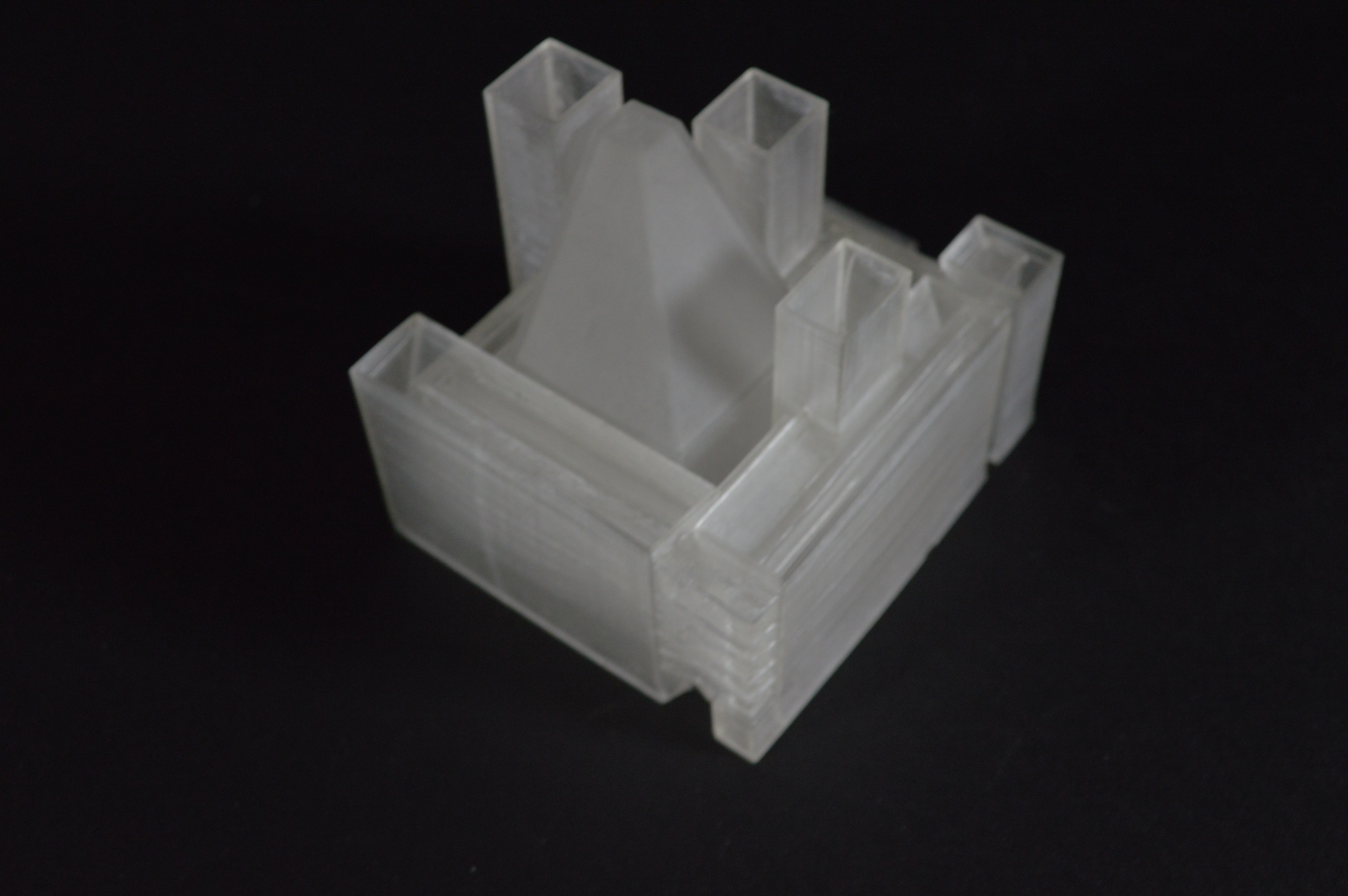
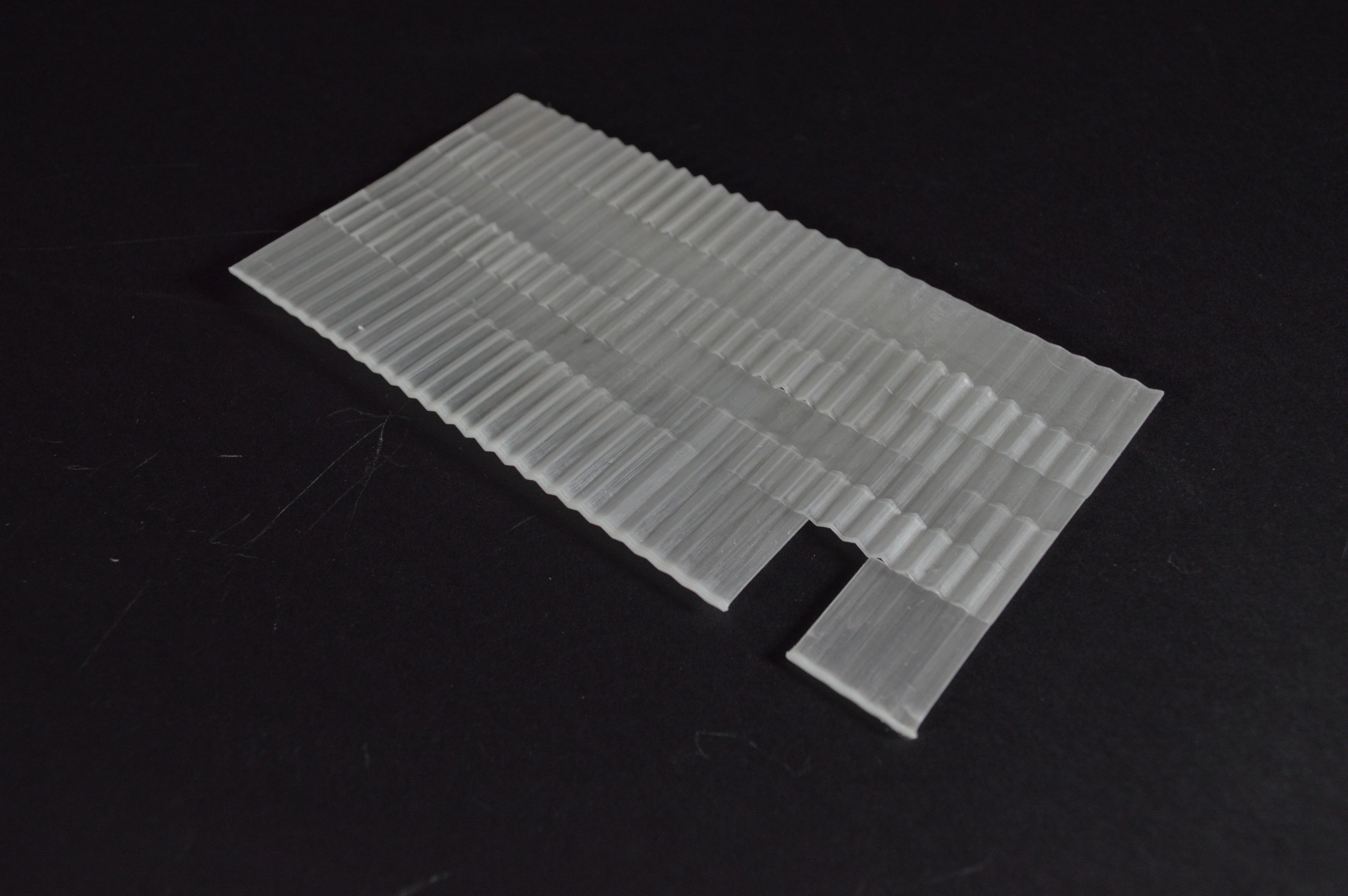
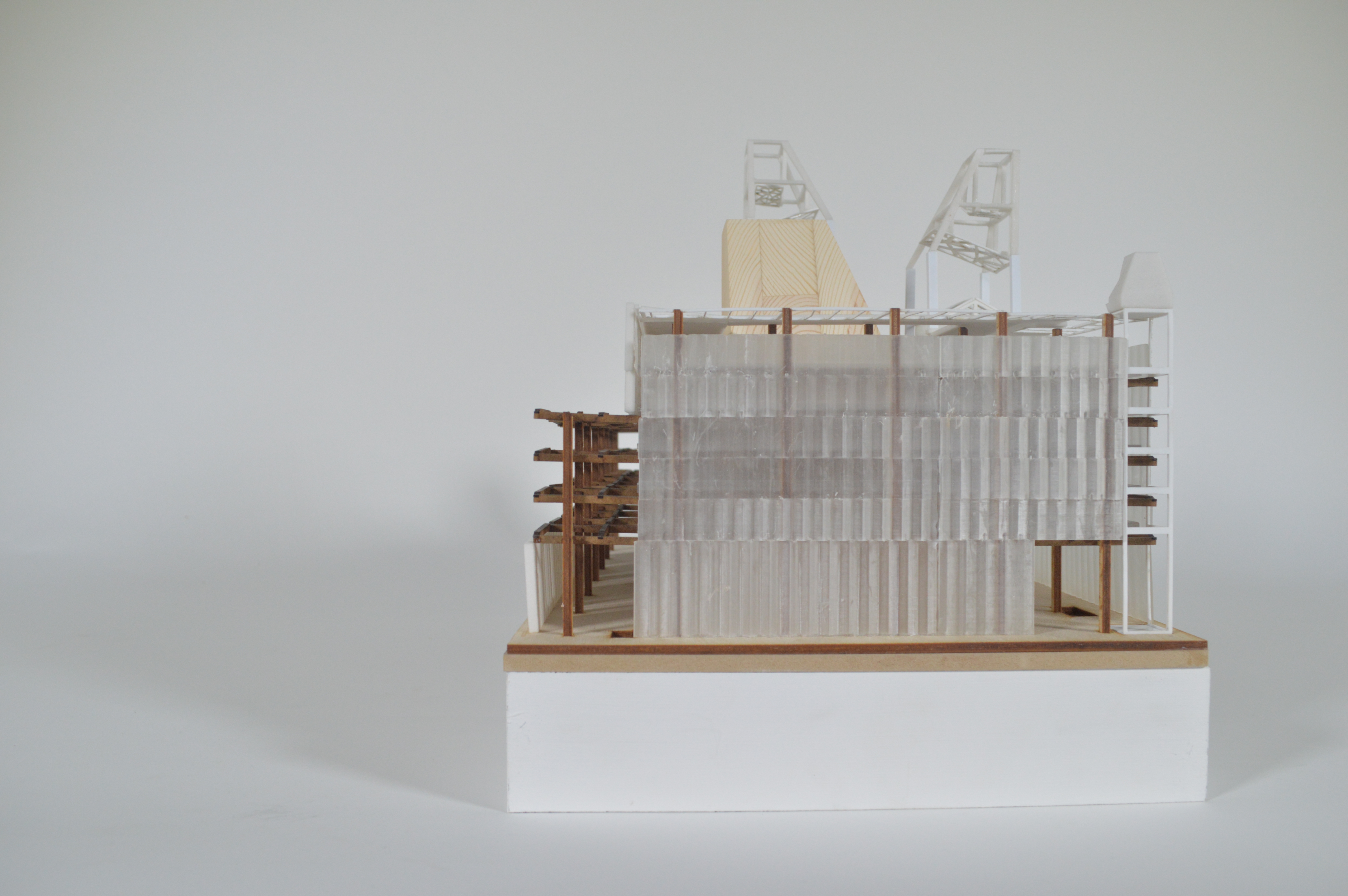
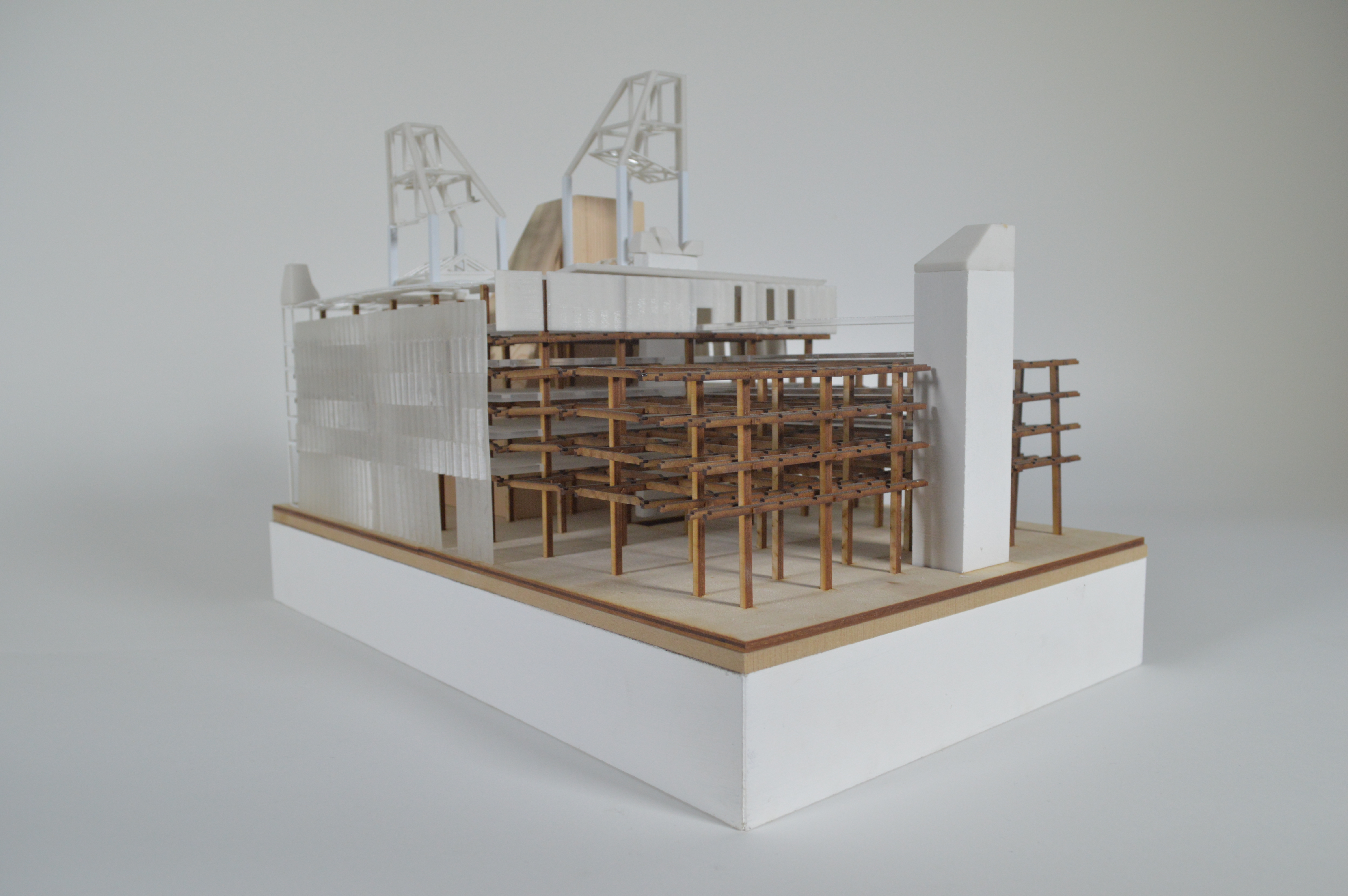
The SLA resin printer is very useful to communicate certain aspects of design due to the material the printer prints with. The printer can use a variety of coloured or clear resins to print. My project featured a separate internal structure within an external frame and therefore the clear resin was ideal for communicating this aspect of the design.

However, to make sure your model is printed correctly, a number of points need to be kept in mind.

DSC_0436

DSC_0448

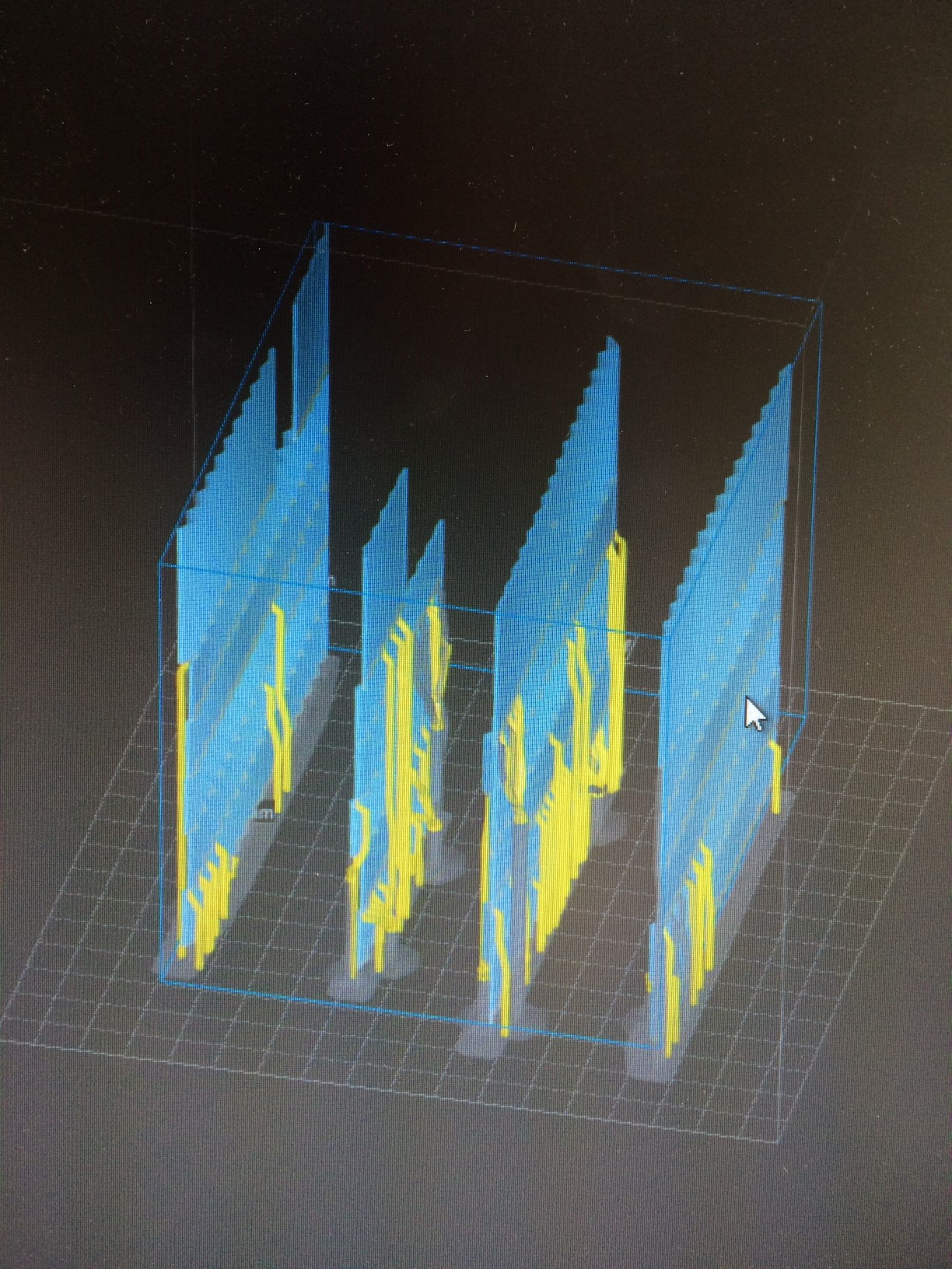
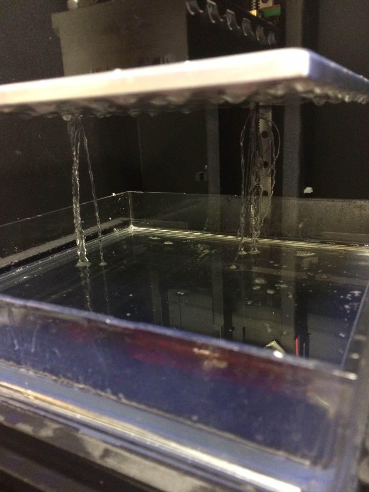
This printer is unlike the ABS and powder printers not only when it comes to material but also the orientation in which it prints. The model is printed upside in layers by slowly raising a platform out of a pool of resin. My models would often not adhere to this base platform and that would cause the print to sag on one side. This might occur due to:

  • Problems with the model (inverted faces, un-welded vertices etc)
  • The base platform not being clean
  • Impurities in the resin
  • Insufficient foundation and support material

image5

Due to the orientation in which the model is printed and the action of pulling the model out of the pool of resin may cause horizontal elements in the model to sag if vertical elements or supports are not introduced at nearby intervals. The floor plates of one of my first resin models sagged towards the inside as there wasn’t enough vertical elements. (This error would not have occurred with the powder printer or ABS printer)

image4image1


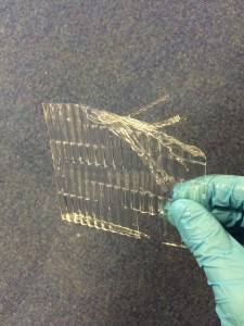
Resin may get trapped inside the model if there isn’t an opening for the resin to drain out of. Again, one my first models still has resin trapped inside it and with resin being slightly translucent, it is visible and may not be desired.

Lastly, since these types of printers are still being tested and perfected, the printers are not perfect yet. Therefore, the printer may just ignore a certain element of the model without any warning. The best ways to get around this I found were:

  • Keep the model as simple as possible
  • Make sure the model is one object before converting to .stl
  • Within the object make sure the faces are oriented correctly
  • Make sure all vertices are welded appropriately

The SLA printer is a very interesting piece of equipment and the finished products if printed correctly look great and work perfectly to communicate exactly what I needed in my project.

– Akhil Mathew 2016

DSC_0464

DSC_0575 DSC_0589


Mouldmaking using Gel-Flex PVC Compound

Anyone who has experimented with casting will appreciate that the process of designing and making the mould is the most critical part of the process. ‘One-off’ simple block or slab casts can often be produced using scrap mdf to create the framework before pouring and then breaking the frame for removal of the completed cast. This is usually successful but can be restrictive in terms of detailing and can often mean destroying the mould to remove the cast.

In order to capture more intricate details of an object we can use silicone rubber which is widely used in the art and design industry. The main drawback of using silicone is its cost and only having one-purpose once it has cured.

A great alternative we are encouraging for testing is ‘Gel-Flex’ PVC Compound which can be melted, poured, cast into and then remelted and re-purposed to make several moulds with the same amount of material.

Monty gel flex tests (2) Monty gel flex tests (1)Using Gel-Flex

At present we are unable to provide a method of melting the compound in the workshop but this product can be easily used at home by heating using a conventional hob or microwaved in a suitable dish (As Monty explains below – preferably glass!). Instructions are provided with the product which you should always read and make sure you understand thoroughly before using.

gelflex

Once the product is in a liquid state it is poured in the same way as with conventional silicone mouldmaking into a box mould over the object you are wanting to cast.

The main drawback to using Gel-Flex is that it isn’t as durable when being used to produce high numbers of casts. Eventually the mould can become over-stretched and can rip. The beauty being that the material can then be melted again and poured to create the mould again – eco considerate and cost effective if you need to mould multiple items.

Monty gel flex tests

Case Study: 1:1 Facade study casts by Monty Dobney

“Gel Flex was great to create the intricate detailing required to for a 1:1 model of my paternated bricks. I first laser cut and glued together (the most time consuming step) an mdf master for the mould to then be covered with the Gel Flex.

After reading the instructions I decided to melt it in a microwave oven, on the first attempt I melted the plastic ‘microwaveable’ container which I had decided to use to melt it in. But two containers stacked seemed to do the trick for holding their form! It was also important to keep checking on it as it can very easily ‘over cook’ which turns it brown (as can be seen in the image below) and a strong burning plastic smell!  I successfully used the Gel Flex to cast from both plaster and wax.”

Monty Gel Flex Tests (4) Monty Gel Flex Tests (5)

Gel Flex is available to buy from 4D Modelshop where you can get 10% student discount or at  Fred Aldous in Manchester and can be found by clicking here.

1:50 Site Model for Extreme Cold Accommodation by Tom Smith

Tom Smith (2)

Recent Part 1 Graduate Thomas Smith was one of the few shortlisted and eventual prize winners in our recent modelmaking award scheme. His project which looks at ‘Fuel poverty accommodation for an extreme cold climate’ balanced the benefits of laser cut components with fine hand crafting to made a crisp clean presentation standard model.

By considering the next steps beyond a medium, in this case laser cutting, the results can be fantastic and the skill and understanding conveyed is self evident.

Tom Smith (6) Tom Smith (8)

“The model conveys the overall structure and form of two of the building typologies I have designed. The elements of the model act in the same way as the structural elements I propose to incorporate.
The finish of the plywood when etched works well to represent the replaceable larch cladding, and the smooth un-etched finish replicated the internal finish of the structures and the walls and floors will all be finished with ply. The clear acrylic represents glass and the polycarbonate shell, allowing me the illustrate internal conditions in terms of lighting.

I feel that I have learnt to ensure that I plan how I am going to construct the model first to ensure that what I want to produce is achievable.”

Tom’s finished model is shown below. We wish him all the best for the future!

Stockport Site Massing Model by Finbar Charleson

This project looks at a site sandwiched between exiting buildings and natural boundaries in Stockport centre. As with most of the projects I have seen Fin work on it’s great to see someone using a variety of media on their desk to inform the decisions in making and in turn use the results to influence their ideas.

As the site includes several large tower blocks it was decided to create the masses as hollow boxes to both save on material and weight of the completed model. The box sections seen here were carefully made up from planes of material – most of it scraps from other projects. 

Once again being concious of material use, Fin designed his contour base to be laser cut into steps with supports as opposed to entire sheets. This again saves material and overall weight. The process requires some minimal extra consideration when producing drawings but the savings are great and well worth the effort. Read more on this method of construction here.

To create the imposing and dominating viaduct feature which spans across the site Fin chose to use a solid mass created from pine. The arches were drawn out and rough cut on the bandsaw before being sanded smooth.  Legs for the viaduct were created as separate pieces with varied heights depending on their position across the contours. The legs were then clamped and glued over night.

Finbar gave us a few words reflecting on the project so far:

‘The model has helped to negotiate a complicated landscaping condition, in that the envelope links three different levels: water, ground and the 1st floor gardens, of a proposed Waste Water Treatment Plant in Stockport city centre. The context is modelled with traditional craft methods as I feel the site has a great sense of history, including the famous  Stockport Viaduct. It has helped to explore sensitive ways of repurposing existing warehouses I used Pepakura software to produce nets of meshes generated in Grasshopper for Rhinoceros, for the initial massing proposals.
The next step is to combine the spatial arrangements of the building with environmental analysis and try new massings on the same model.’

The completed model has a removable site section to allow different proposals to be inserted into context. Fin has already made several suggested forms from card as seen below. Finbar Stockport Model (15) Finbar Stockport Model (16)Finbar Stockport Model (18) Finbar Stockport Model (17)


‘Lithification’ 1:200 site model, James Taylor-Foster

As part of the final major project for his 3rd year submission James decided to produce his completed concept for the former Odeon cinema site on Oxford Street in Manchester at 1:200 scale.

James described the project for us below:
This project is, fundamentally, a house for stone fragments in the heart of Manchesters civic centre. Combining gallery spaces with workshops for stonemasonry, the buildings programme hinges around a tripartite relationship between stone as symbol, material and object. The spaces which consolidate these three spatial threads create a communicative dialogue between street and threshold, node and surface, alongside person and occupation. Designed to activate encounters between the material fabric of the built environment, movement of people, and the intimate craft of stone carving, the scheme seeks to integrate with (rather than reconfigure) the symbolic fabric of the city. The scheme, heavily influenced by ritualised occupancy both human and non-human (such as the daily, repeated zenith of falling light), distills the principle elements of a building into a collection of interdependent, intangible relationships. Volume, void and light align to create moments of lateral swelling in which the interaction of people supersedes, yet elevates and accentuates, particular formal moves. Capturing these ideas in a model was a challenge. Using a lightly grained wood, jelutong, to mass the large volumes of space, 3D printed elements bring focus to two elements: the entrance loggia in the centre of the building and the facade that faces Oxford Street, a busy Mancunian thoroughfare. In using a modest palette of materials, focus is drawn to the relationship between these two key elements that activate the street and public space they face. All sat on a heavy mahogany base – elevated by a thin sheet of plywood which denotes the street kerb – this simple, diagrammatic, 1:200 model works alongside a collection of drawings to visualise a complex orchestration of space. (James Taylor-Foster 2014)

Due to the fragile nature of the powder printing material when used in thin volumes there were several breakages to smaller elements of the model. These were repaired using a mix of styrene strips and filler. Once repaired the whole model was reinforced by soaking it in superglue and finished with a coat of white paint. It is always worth remembering that the smaller details of designs are a potential break risk for 3D powder printing. If possible try not to produce components smaller that 2mm in size and thickness. You should always consider the removal process and how this will be successfully carried out given your design. See more of James’ work by clicking here.

How to Save Money and Materials when Making Contour Models

Just before the Christmas break I made a post about the benefits and importance of concious planning and material consideration when thinking about your models. Here is a great example carried out by a group of 3rd year students over the last few days.

This group set out to produce a contour model of a site they have been given to focus on for redevelopment. They took the time to approach us before starting to plan their model which resulted in a huge saving for them in cost and in the materials saved.

Rather than using entire sheets of MDF to build up contour layers We suggested they amend their drawing to construct the contours using the ‘step’ method. This means reducing each contour piece to a fraction of the full sheet size with the only non visible area being a small step to which the piece above can be fixed.

Out of the original materials estimate of 25 full 4mm x 800mm x 450mm sheets for the main contour section of the model the amended drawings helped to decrease this number to just 6.

At the current cost of £2.50 per sheet, the original cost of material for this part of the model would equate to £62.50. After redrawing the file and planning each cut sheet the 6 sheets required cost just £15. A huge saving of £47.50 and 19 full sheets of 4mm Medite MDF.

As you can see it is well worth taking the time to evaluate what it is you are producing and the necessary material required. A good place to start is with your tutors, Jim and myself who are dealing with this subject matter everyday.

Scott


City Master Plan Models

Making continues this week in the workshop with most students focussed on creating city master plan models.It can be helpful when making master plans to lay out scaled plans to place components in place and ensure everything has been cut. If you want accuracy it is essential to have well scaled plans printed to understand the size of your project on a bench in front of you.
When dealing with master plan models more often than not you will find an abundance of components littering your desk space. The best was to keep track of these to is to order them and separate them into districts. This may suit a group project as individuals can be given responsibility over separate areas of the model. This group used plastic bags to distribute components as they were cut to avoid mixing them up.

Here Jim is using the band saw table on an angle to create roof pitches on a block model. It is likely that when producing block models there will come a point when a machines limits will not be sufficient to get the angle you require.

Overcoming these aspects of modelmaking can be time consuming but is of course necessary to ensure consistent accuracy of your models. Should you feel you’re unsure about how to achieve a particular angle don’t hesitate to ask our advice.


Urban Food Flow Model, Sophie Smith

To demonstrate her ideas for rebalancing food slow or supplies in the city Sophie used an unorthodox approach to demonstrate her proposal. Using wire to convey possible food output areas of the site are highlighted using coloured acrylic and linked. The main focus is around an existing supermarket with the intention being to show how redistribution of suppliers could be increased locally.Living water cress troff’s are used in places of significant produce making this a living model – fairly unusual but interesting approach!

3rd Year Structural Detail Models

Designing a building requires attention to every detail. This attention must take into account the limits of construction materials and how they can be managed an assembled in reality.

The only way to do this well is to have a good understanding of construction and material mechanics. Structural detail study models allow us to focus on specific junctions of framework and often bring potential problems with assembly to our attention.

Whilst it is very important that you, as an architect in training, have a thorough understanding of building materials. These models should not focus too much on the 1:1 ‘real world’ materials. Your area of study is in understanding how components interact or don’t interact with each other in terms of their physical shape. Testing material strengths, weaknesses and compatibility for a particular role requires much more in depth study and often more space than our workshop can provide.

The models shown on this post are made to mimic real materials to reduce weight and construction restrictions whilst still conveying their assembly effectively.

1:500 Master Plan Model, Year 3 BA Architecture

This group project for 3rd year BA students will be used to display multiple concepts that will continue to develop throughout the year. For this reason considerable thought was put into getting the contouring and overall model size correct for purpose.

By figuring out high and low points on their site the group could then make a series of supporting ‘ribs’ at the relevant size for the 1:500 scale. Clearly marking each piece by number is crucial when there are many components. Once fixed in place the engraved ‘skin’ was fixed over the top creating the flow of contours across the site.


The next main phase of construction was to produce the existing site buildings. by taking plans printed at scale the group divided the site into different zones and gave each building a number to assure easy identification when assembling.

By referring to visual reference such as photographs it is possible to find an approximate building height by looking at courses of brickwork and door/window heights. At this scale approximations are fine for the models purpose but extra care should be taken when focussing on areas in the immediate vicinity of the areas being used for proposed development.

The group decided to add extra laser engraved facade details to the exiting buildings closes to their proposed site. This helps to highlight the concentration and detail in the surrounding buildings without over emphasising their physical construction.

As the group found out, adding too many detail lines can prove costly in terms of time on the laser cutter.

We encourage you to consult us about any of these fine details as more often than not they can be simplified and still easily convey the message.