Earlier this year we were approached by Hawkins\Brown Architects to host a CPD session for their Manchester office, several of whom are Alumni of Manchester School of Architecture.
This gave us the opportunity to consolidate our current approach at MSA and present the idea of model making in a new inspirational light.
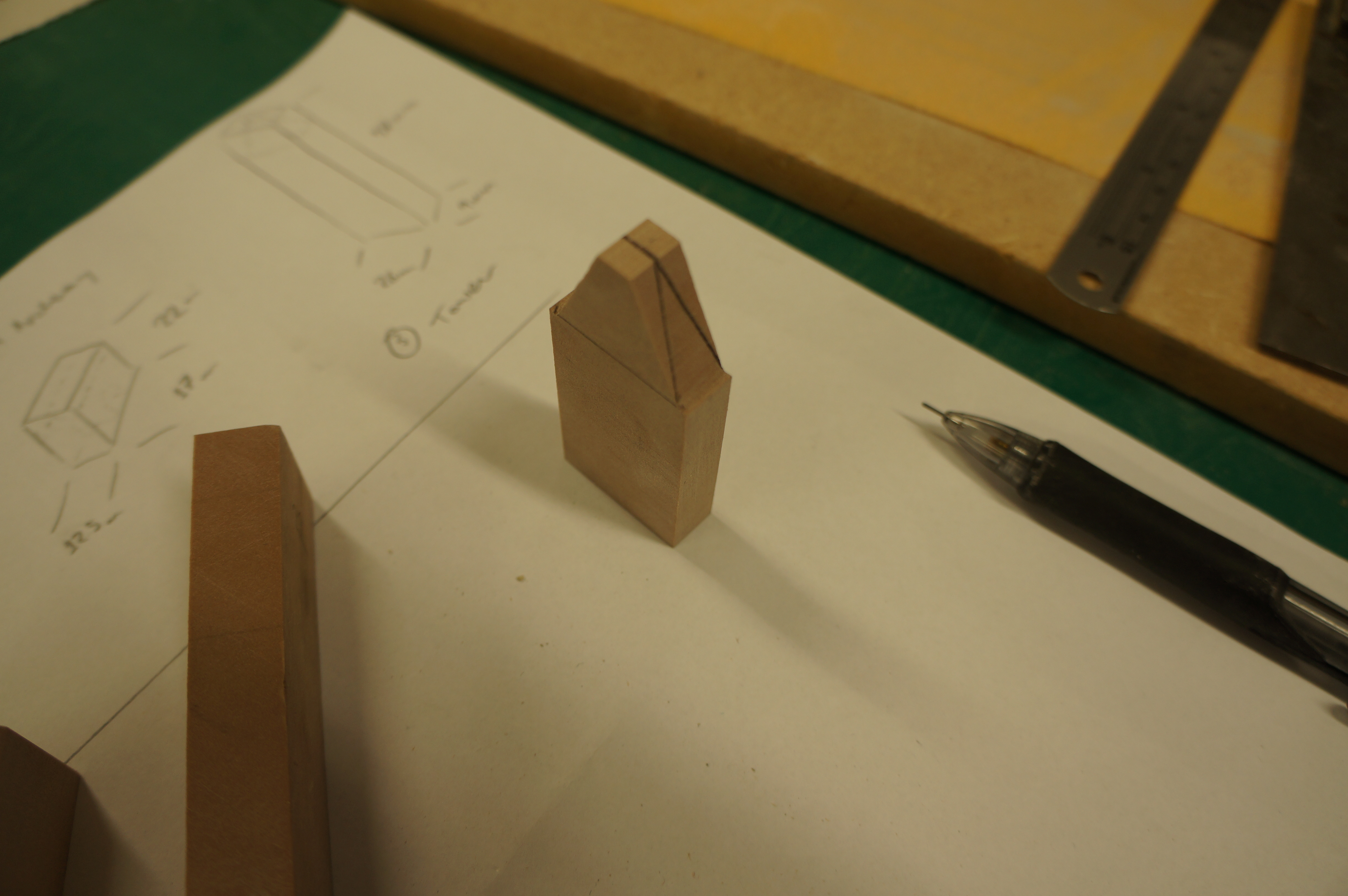
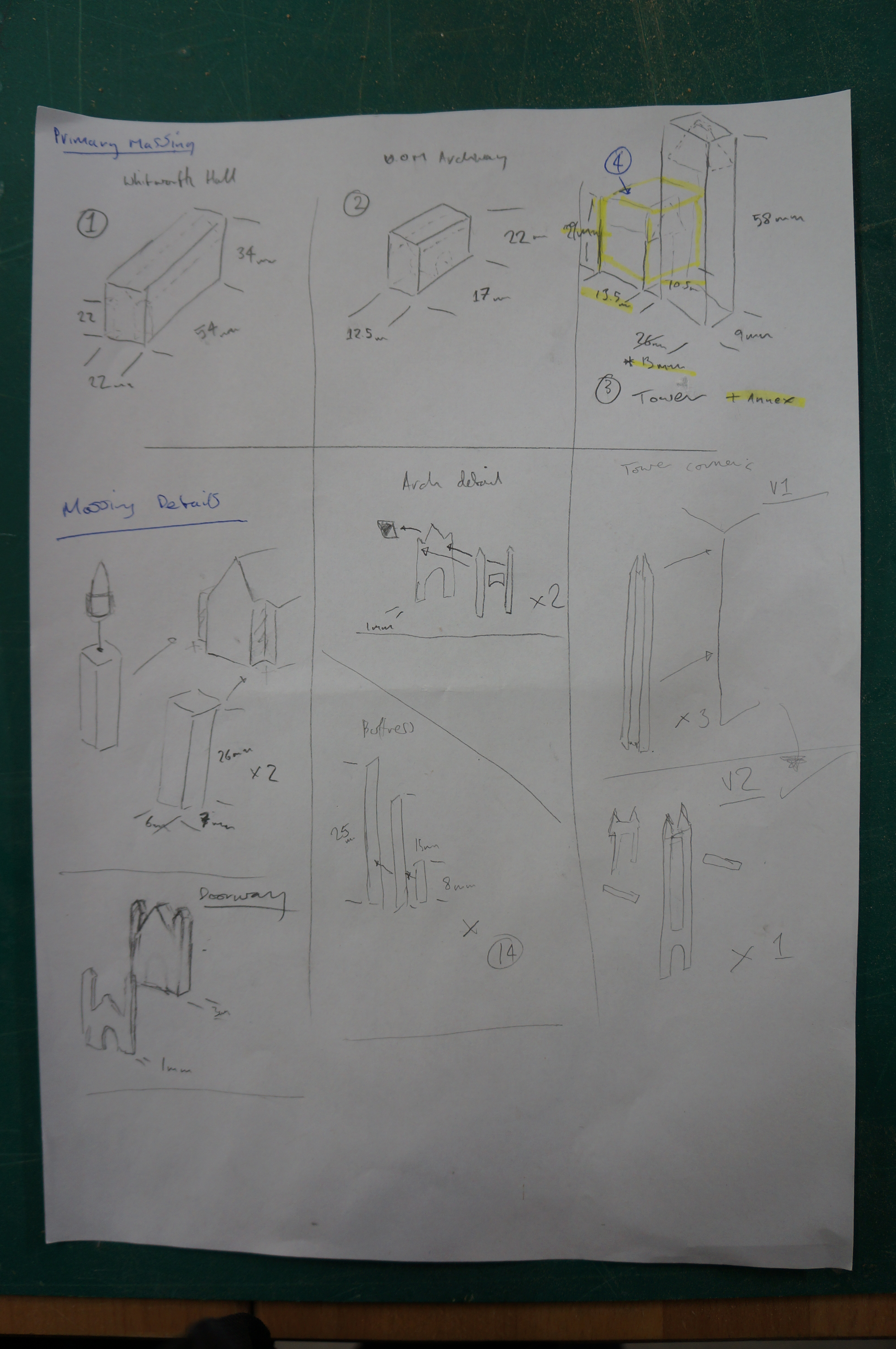
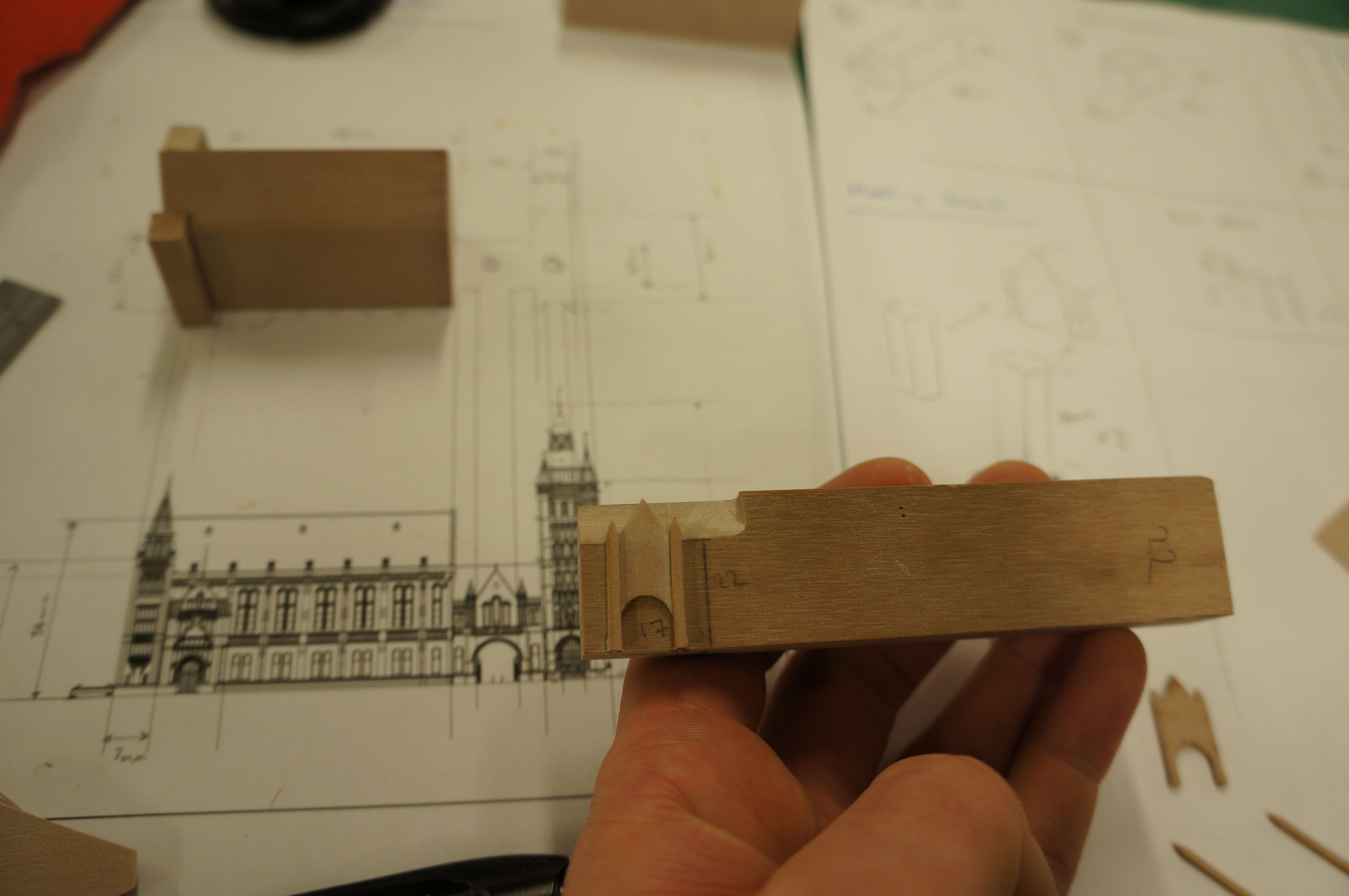
Much like our approach to tacking problems in the workshop we began by getting to the heart of the subject. Looking at the origins of the craft we asked ‘where did it all start and why?’ The craft’s background bares many similarities to our current thoughts and reasoning behind modelmaking. The physical model is viewed as an embodiment of ideas, beliefs and values to be read by others.

Our presentation followed the timeline of history, using ancient and classical precedents to modern day applications in architectural practice, portraying the changes for the maker and architect. Expanding on our exploration, we asked Hawkins\Brown to tell us their views from a project level and their thoughts on the future of modelmaking in practice. We gain an insight from Hawkins\Brown Architect and MSA Graduate Jack Stewart who has a keen interest in the ever evolving relationship between physical modelmaking and digital fabrication.
“I’d bet there isn’t a single project that makes it through Hawkins\Brown without at least one model being produced for it.
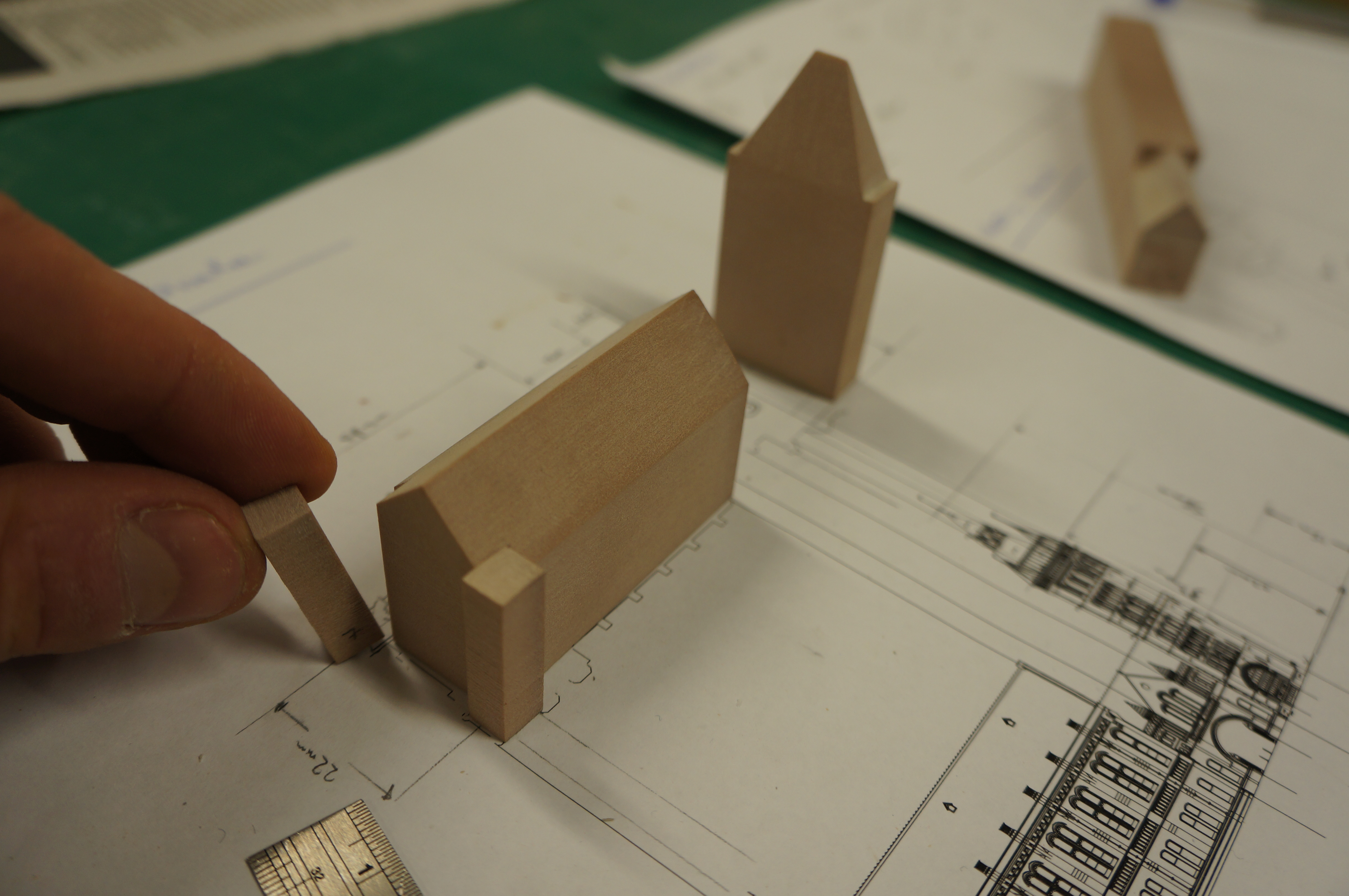
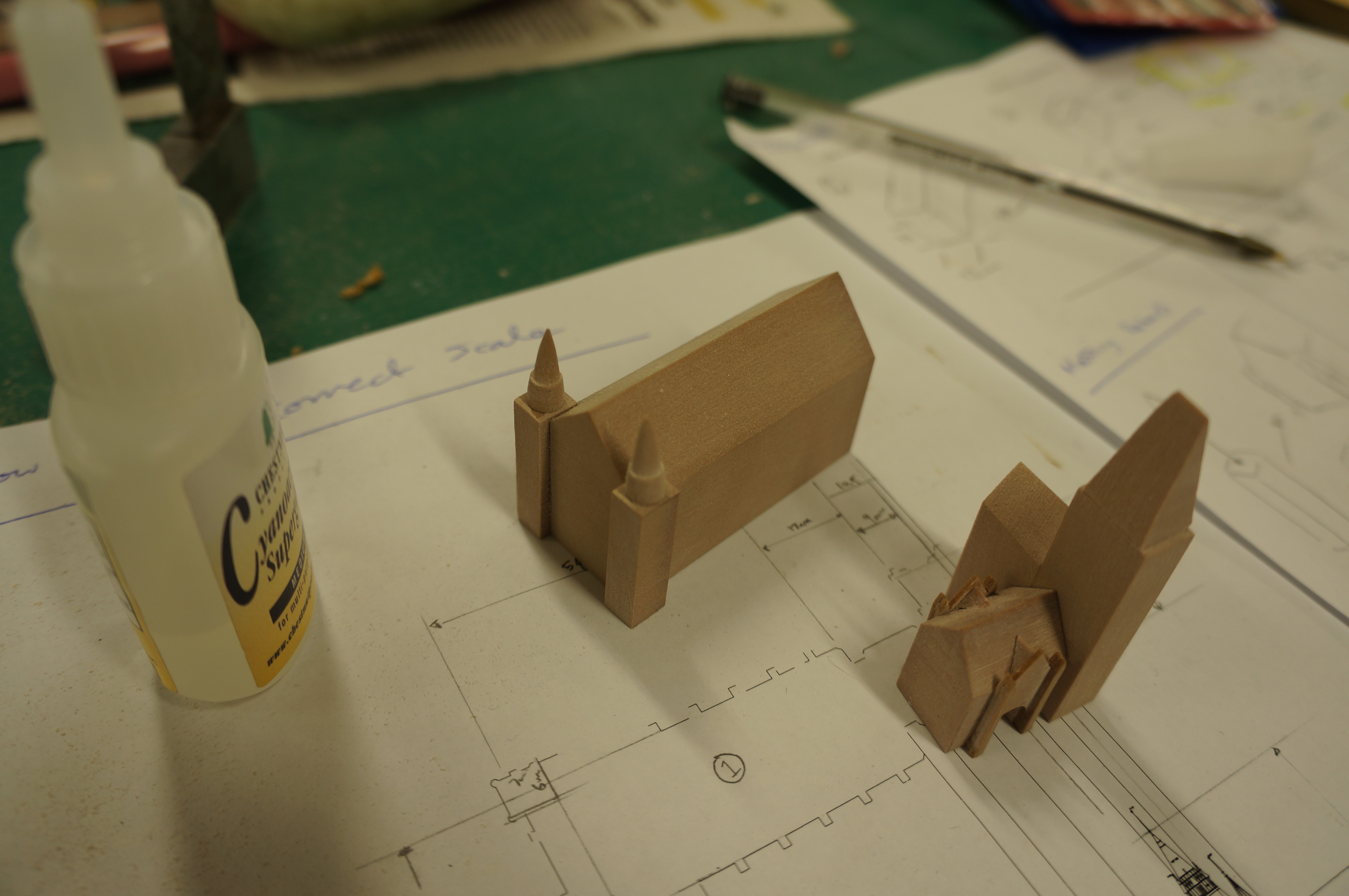
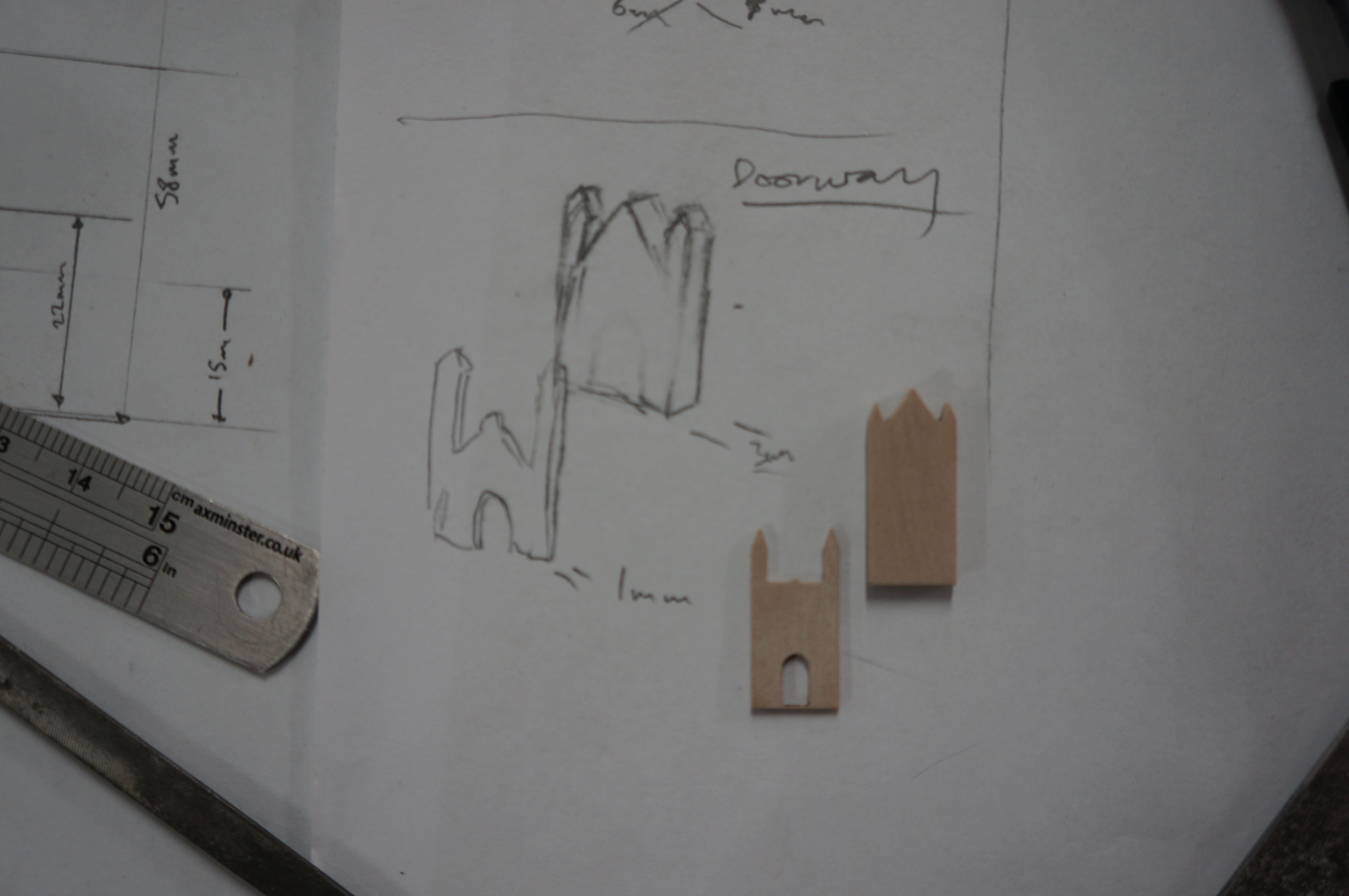
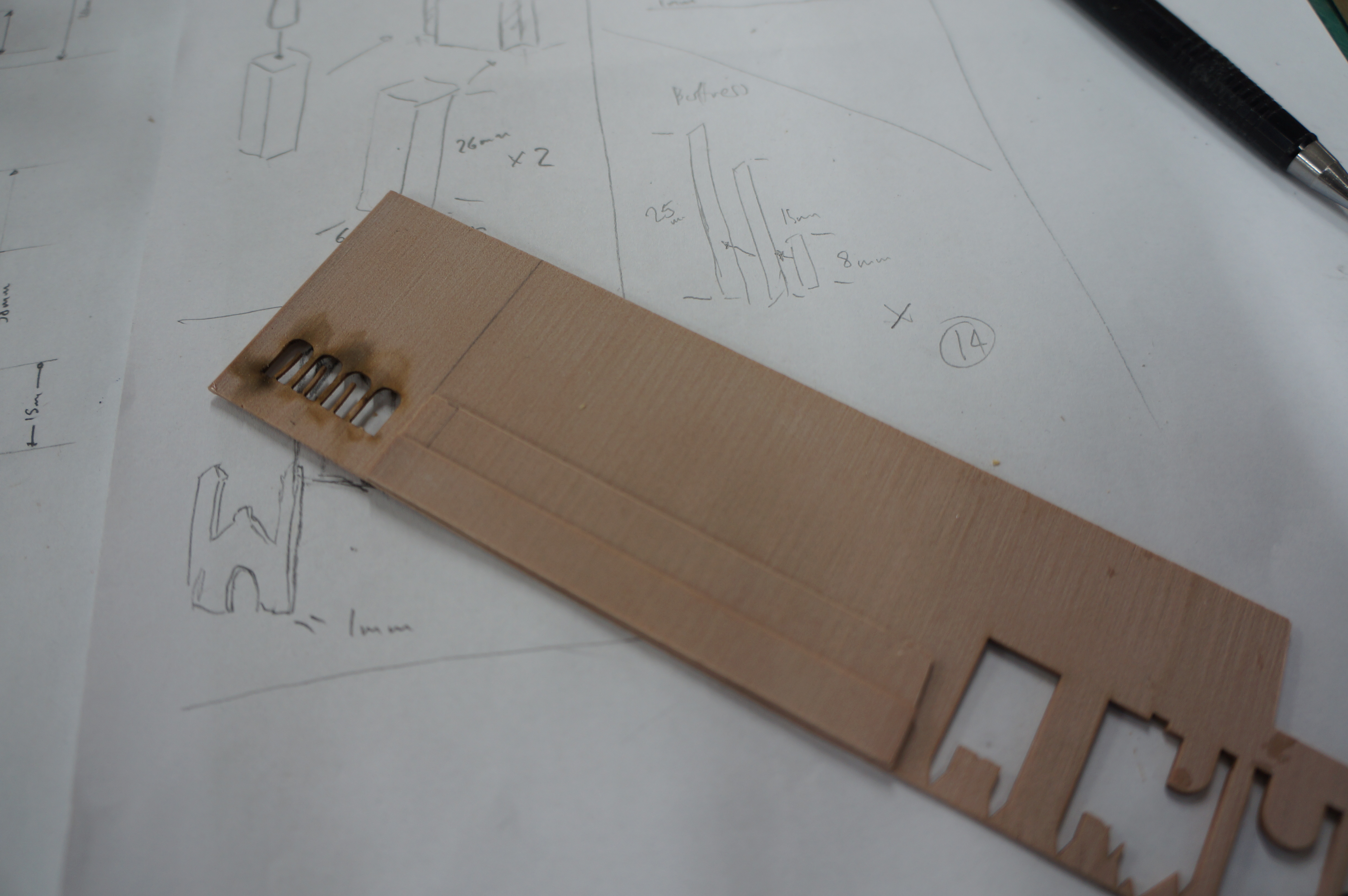
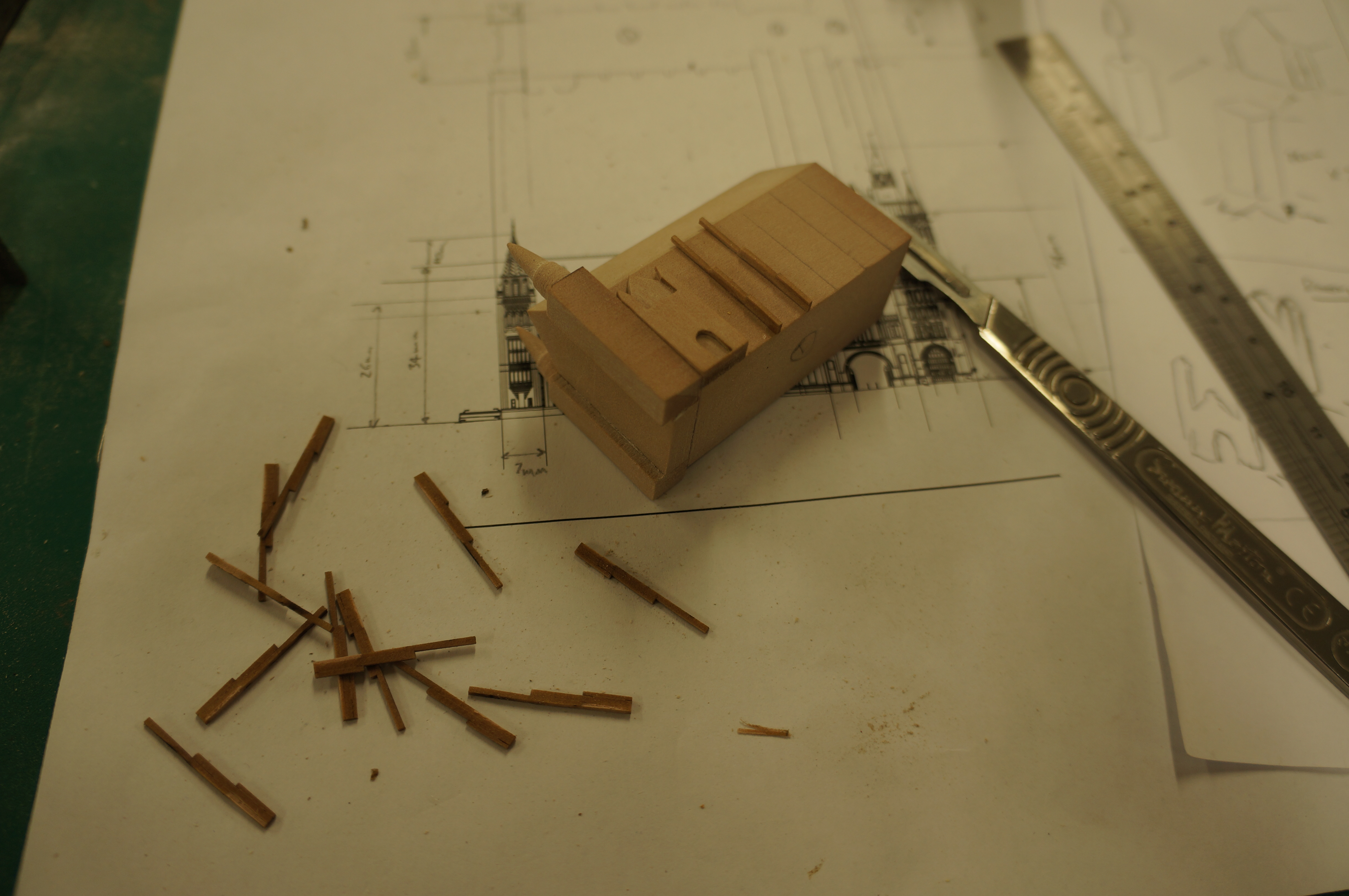
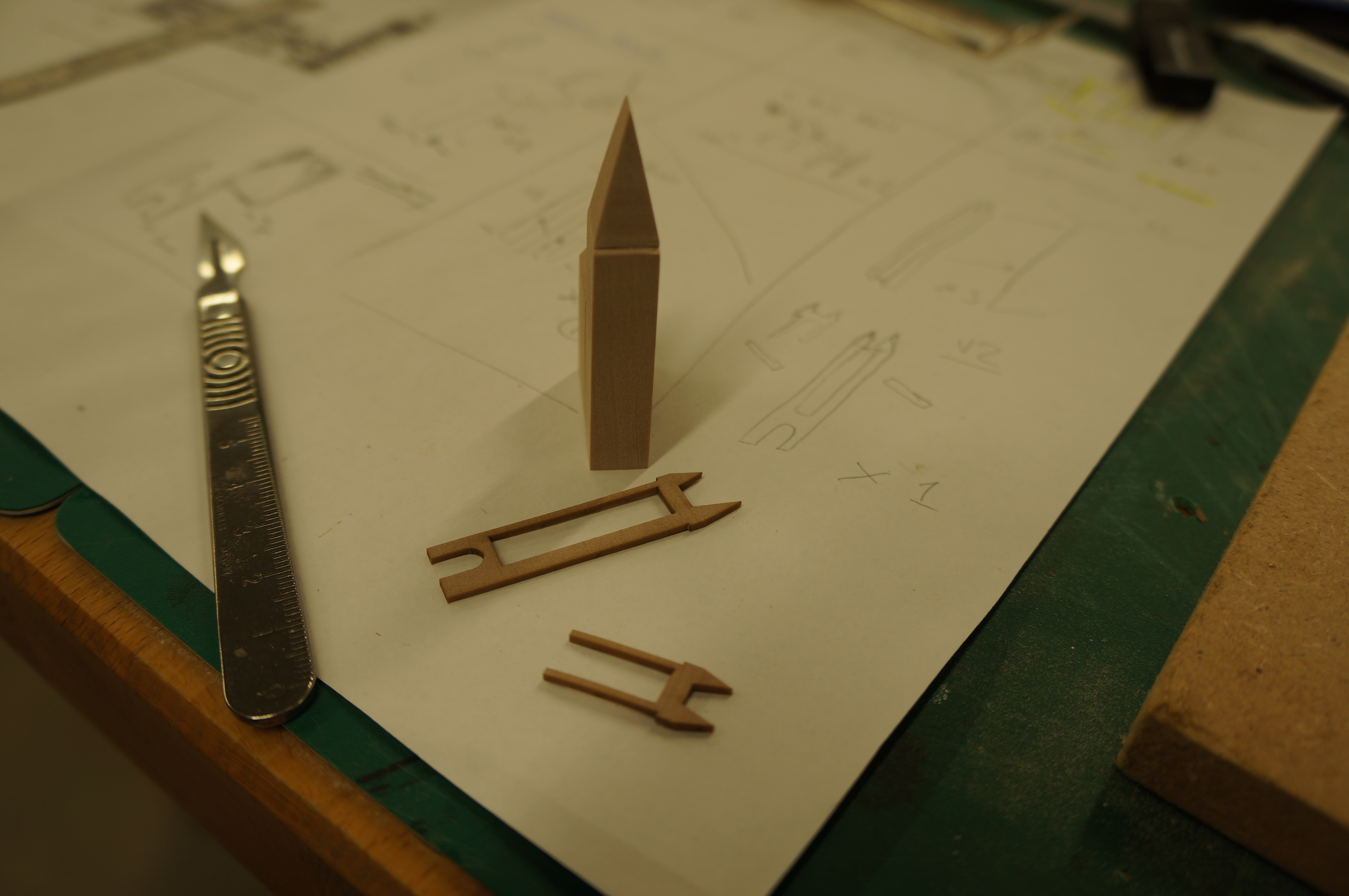
We can make models for all stages of projects and using models as design tools is an essential part of our process. Quick sketch models are invaluable to explore our ideas in three dimensions with design teams. Whilst these and more polished models are fantastic tools to help describe schemes to clients and sell schemes to stakeholders or consultation groups, such as planning. Clients love handling a tangible three dimensional object and we love testing them”
Education and Practice
The idea of making in practice is something that many of our students wish to continue and in many cases would gladly devote a lot of more of their time to. This often raises the question of how this ideology can be and is fulfilled in practice. What can come as a surprise is the broad selection of styles and scales of model making that is actively used in practice everyday.

For example Hawkins\Brown have just invested in a new modelmaking workshop space at their London base and have a designated maker space at their satellite Manchester office which recently celebrated its 1st year of work.
“Historically we have relied upon design teams to construct their own physical 3D models and when a particularly onerous or complex model has been required we would outsource this to a specialist model maker. We don’t anticipate the latter disappearing, but we do value the close link between our design teams and the models that they are using. As such we have recently employed an in-house model maker. We’re at a size now where an in-house model maker is really valuable to help educate on model making techniques, explore more possibilities, maintain the equipment that we have in-house and make the connection with external resources for machines and materials that we don’t have in-house. We anticipate this will help to take our in-house models to the next level.”

What is particularly encouraging about this approach is the value given to the craft of model making and the potential for those within architecture to utilise the skills they have learnt within their education.
“[Our] design process doesn’t follow a company standard. Every project is unique creating a unique series of design challenges. Like the adage says, ‘there are many ways to skin a cat’, it is up to the individuals within a design team to decide how they would like to best approach a design problem. In many cases this results in the creation of a physical model.”

Working space
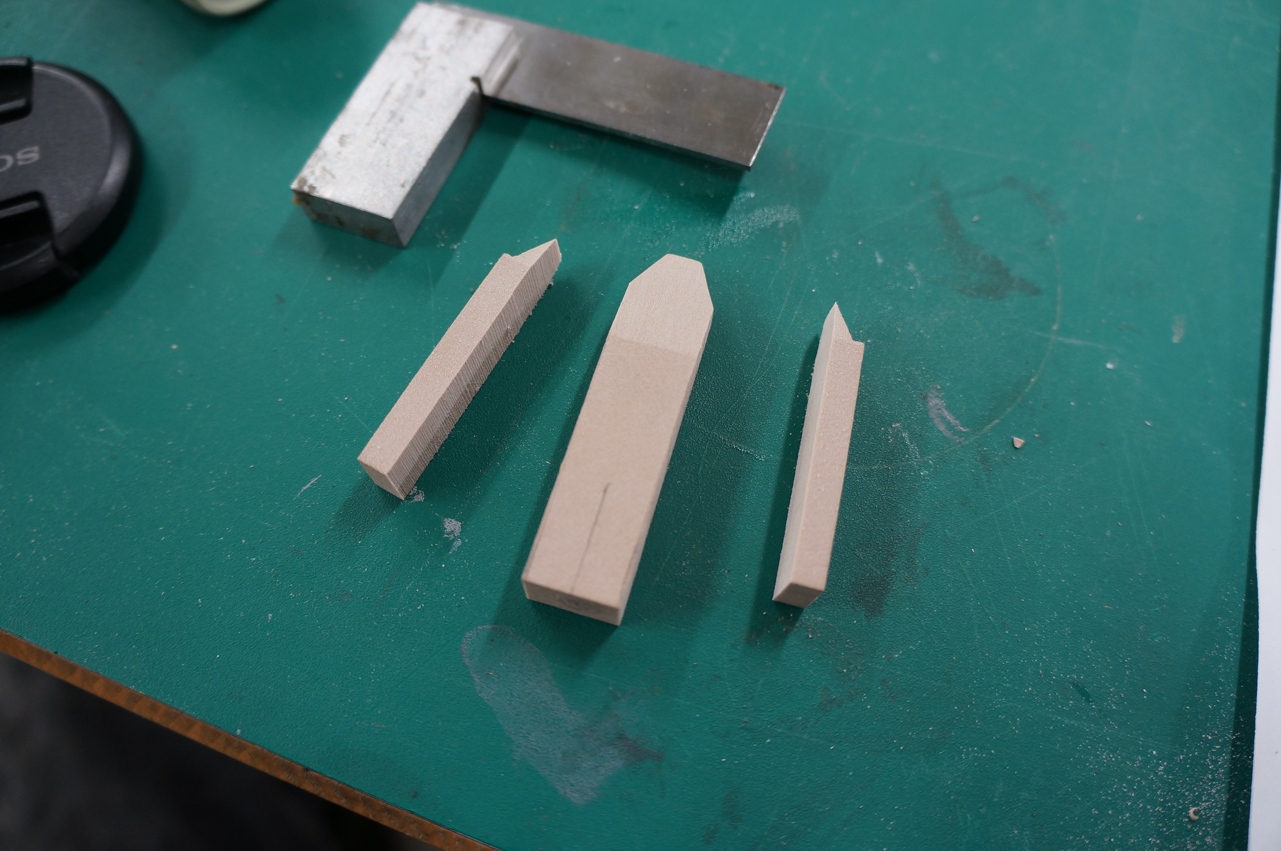
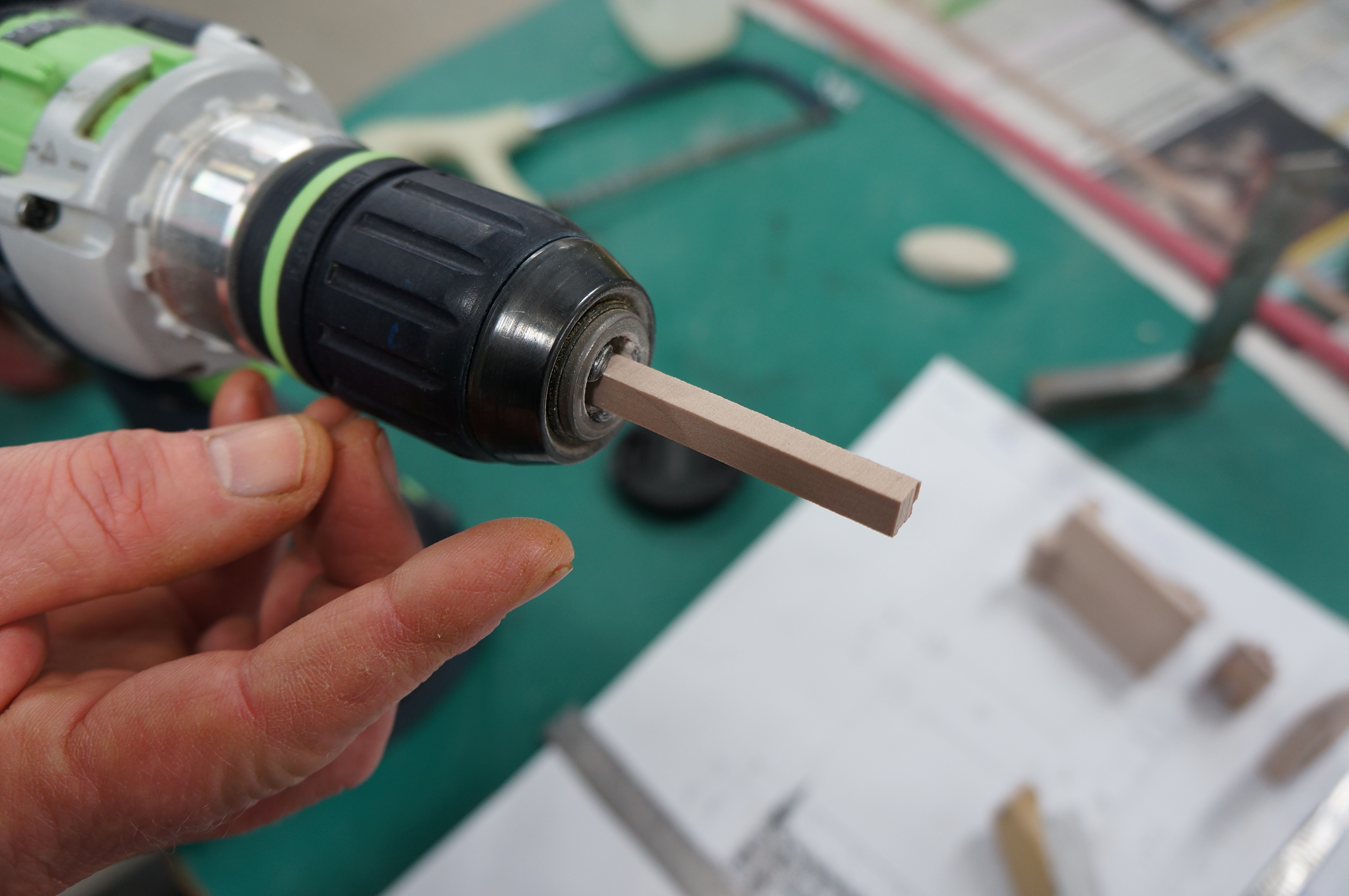
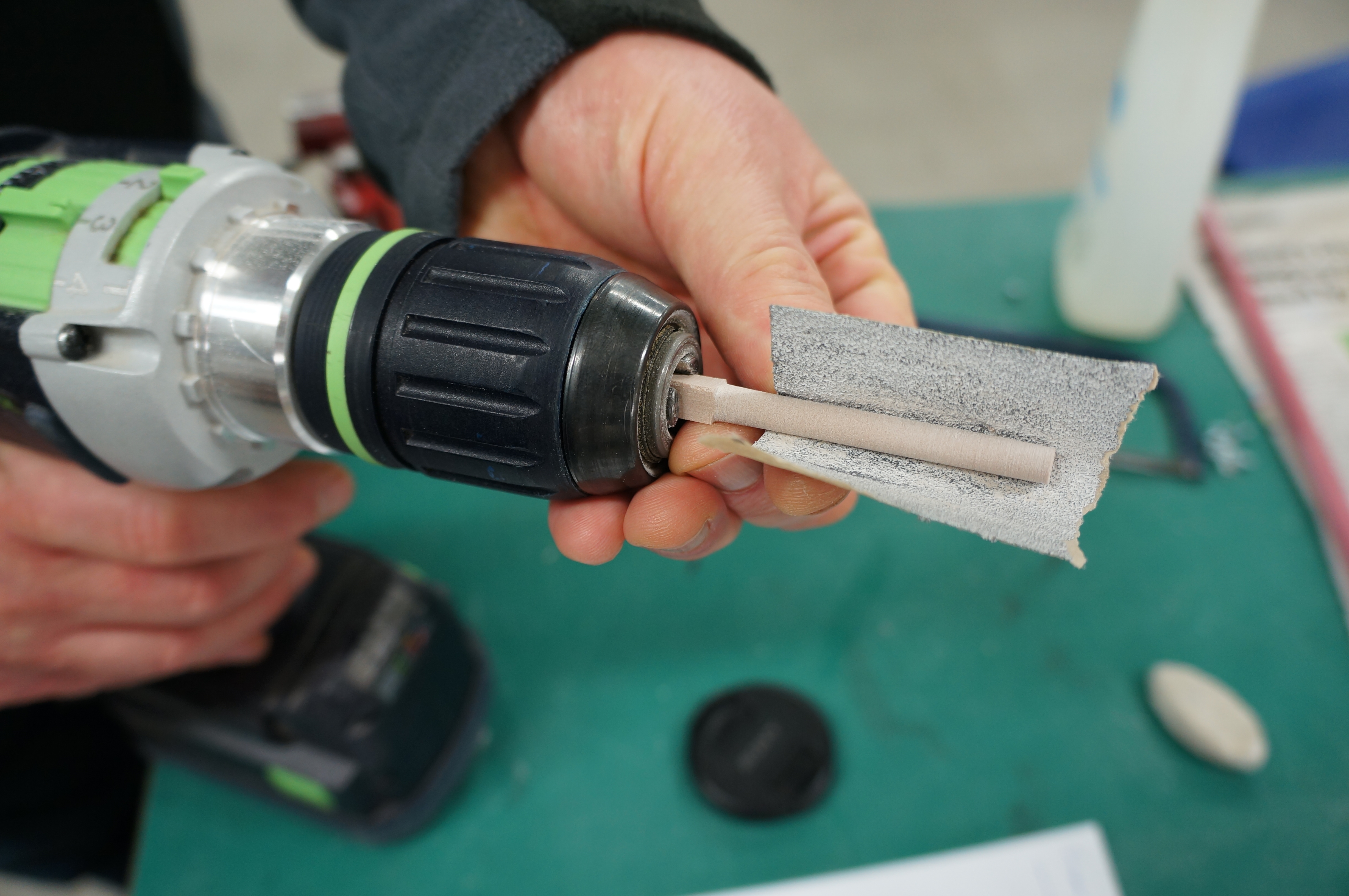
Having worked in several different modelmaking companies and visited many different workshops, no two set-ups are the same. Finding a balance of the appropriate tools to fit out a workshop is instrumental in making each output achieve its intended purpose. Hawkins\Brown are striking this balance between hand craft and digital fabrication.
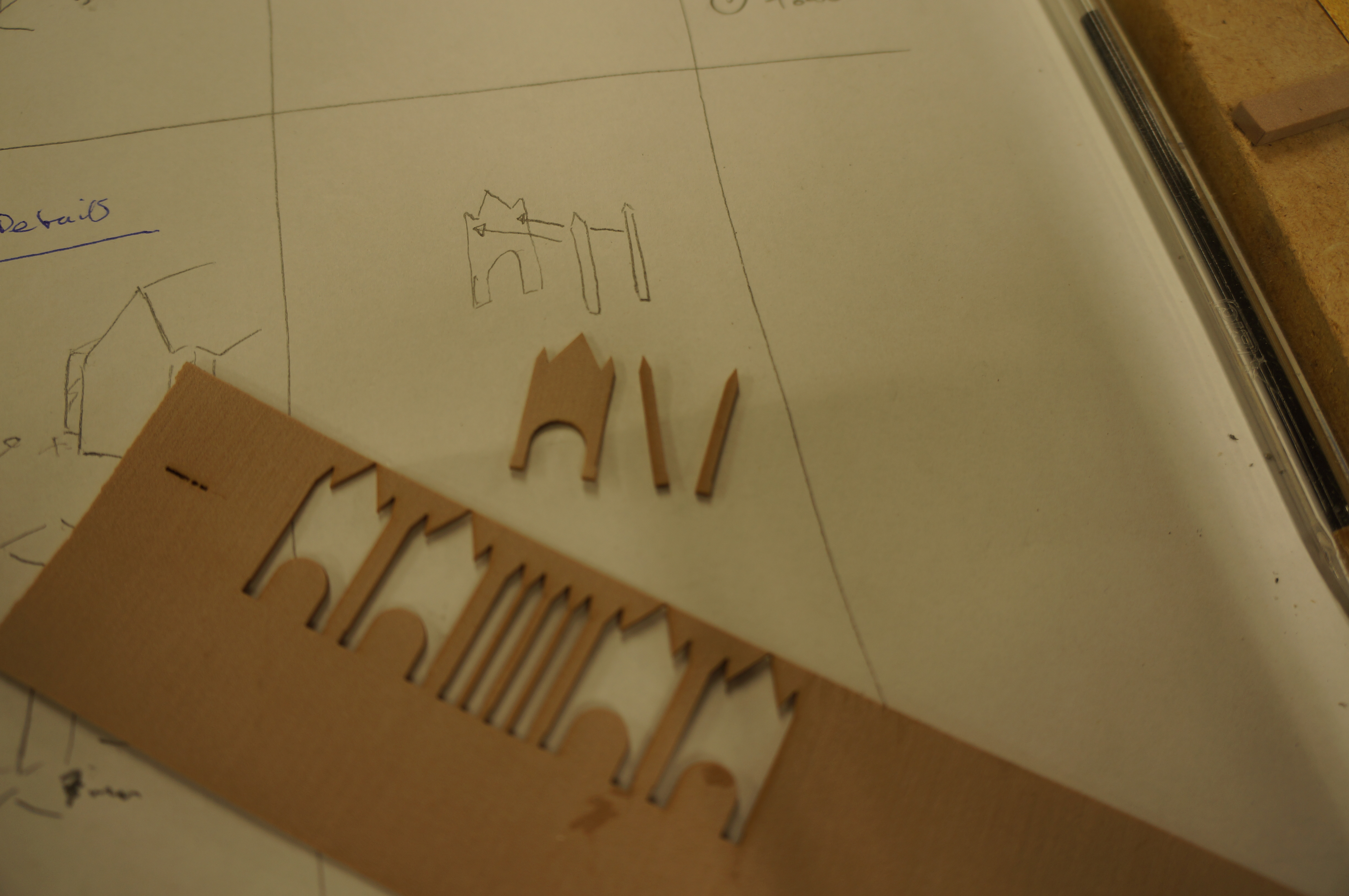
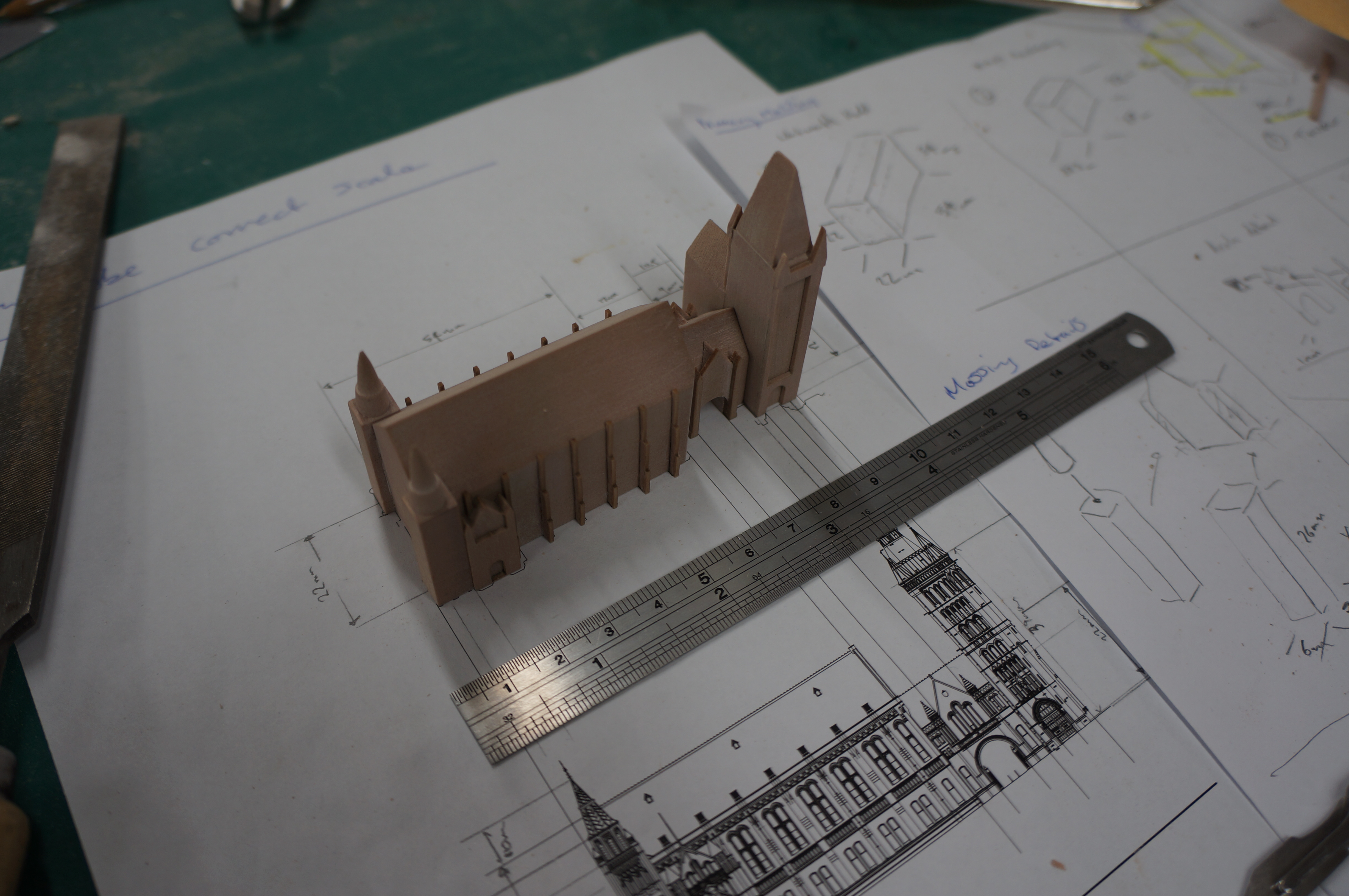
“We have much of the more traditional facilities and equipment such as cutting mats and tools for thinner sheet materials, hot wire cutters for foam models and numerous typical working tools for material preparation. We invested in a laser cutter four years ago, which further increased our ability for model production.”
The company have also recently purchased a ‘MakerBot’ and ProJet360 Powder printer with a view to speeding up the production of complex forms that can be deemed too time consuming for traditional making techniques during design development. Time, or a lack of it, is certainly a major consideration when it comes to the application of modelmaking in student submissions. The increased pressure for a variety of submissions at once allows little time to learn through making. This is something that we strive to improve upon, though how is this considered in practice? How does project time factor in allowance for modelmaking requirements? Jake Stephenson is a recent part 1 architect working at Hawkins\Brown who has continued modelmaking into practice.
“[Modelmaking] is very important and affirms what we learned at university about the process informing the design. In practice [modelmaking] goals are usually a decision made between myself and the project architect about when it would need to be completed by. Being realistic about my own time and skills as well as how fast a model would can be created. It’s very much about my awareness of time scales; booking laser cutting sessions, getting files ready – then allowing enough time to build my model for the deadline we set ourselves.
When it comes to costs it’s about giving options. For example when doing an iterative sketch model, I would use cheaper materials, compared to a model that is to show the client where the budget would generally be bigger for material costs. We would always try to source the cheapest most effective options by checking with multiple suppliers to get the most for our budget.”

Thoughts on the future
There are many perceptions of what it is to practice architecture as we are reminded daily in our workshop and without fail at every university open day. If we were to give a cross section of the questions we were regularly asked by prospective students and their parents it would invariably bring up something about technology and CAD driven machines. The awareness within the general public has increased due to the shift in accessibility of mainstream manufacturing techniques and prototyping. It’s important to remember that much of this stereolithographic technology is not as new as so often perceived. What has changed in recent years is the relative ease for interested parties to use it. This has led to an almost universal expectation that these mediums be made available in education and that accessing them is a given and large part of modern learning.
Our responses to the often broad enquiries in the area of 3D Printing and Laser cutting often lead us to ask a lot of ‘Why?’ based questions. ‘Why are we setting out to make a particular object and why do you believe such a machine can get you to that goal?’
Our concern and reasoning here is in the misuse of technology as a learning tool. There is often a strong desire from students to depend upon it without understanding their own intentions or purpose of their exploration through the model. We advocate the work ethos to our students to stop and think before diving straight in.

For Jack Stewart, having a strong interaction between traditional and contemporary data driven approaches is very important for successful outputs and effective learning within the Hawkins\Brown team.
“With BIM becoming ever more prevalent, in the construction industry, digital models for detail production and delivery of projects are becoming increasingly important. But how we generate the forms and arrangements of our buildings, at a concept design stage, benefits hugely from both digital and physical modelling too.
For CAD modelling it is a particularly interesting domain. A model that perhaps begins life as a simple massing study will evolve, through to construction, usually through numerous separated studies. However now, through using emerging generative modelling technology, this entire process can potentially be captured in one software tool. The possibilities here are that decisions made, that are dictating early design principles, could in theory be amended much later in the process with all subsequent detail updating accordingly. This is possible as more sophisticated digital models geometries can be defined as a series of design decisions that are stored as data, rather than statically sculpted ‘dumb objects’.
The benefits of models stored as data is the ability to translate this data, quite easily, into something else – something physical. And with the accessibility of rapid prototyping and the machines described previously the connection to and knowledge of these machines will likely become increasingly important. The techniques and skills needed for model making will certainly grow in this regard. Whilst the skill required to manually craft materials into beautiful models, should not be lost, I believe future model makers will become even more well versed in intelligently generating CAD models and then streamlining these for fabrication. Here I see the boundary that we define between digital and physical models, and between designer and model maker, changing.“
Putting together our initial presentation for a CPD has been a good opportunity to reflect and analyse our beliefs about modelmaking at B.15. With the ongoing digital shift in architecture, the role of the architect is changing and architectural education needs to respond to that. Graduates who can identify the best means to explore their ideas through proven skill will be more sought after than those who solely depend on technology to make their decisions. Our ongoing discussions with Hawkins\Brown have proved insightful and we look forward to working more with this growing practice.

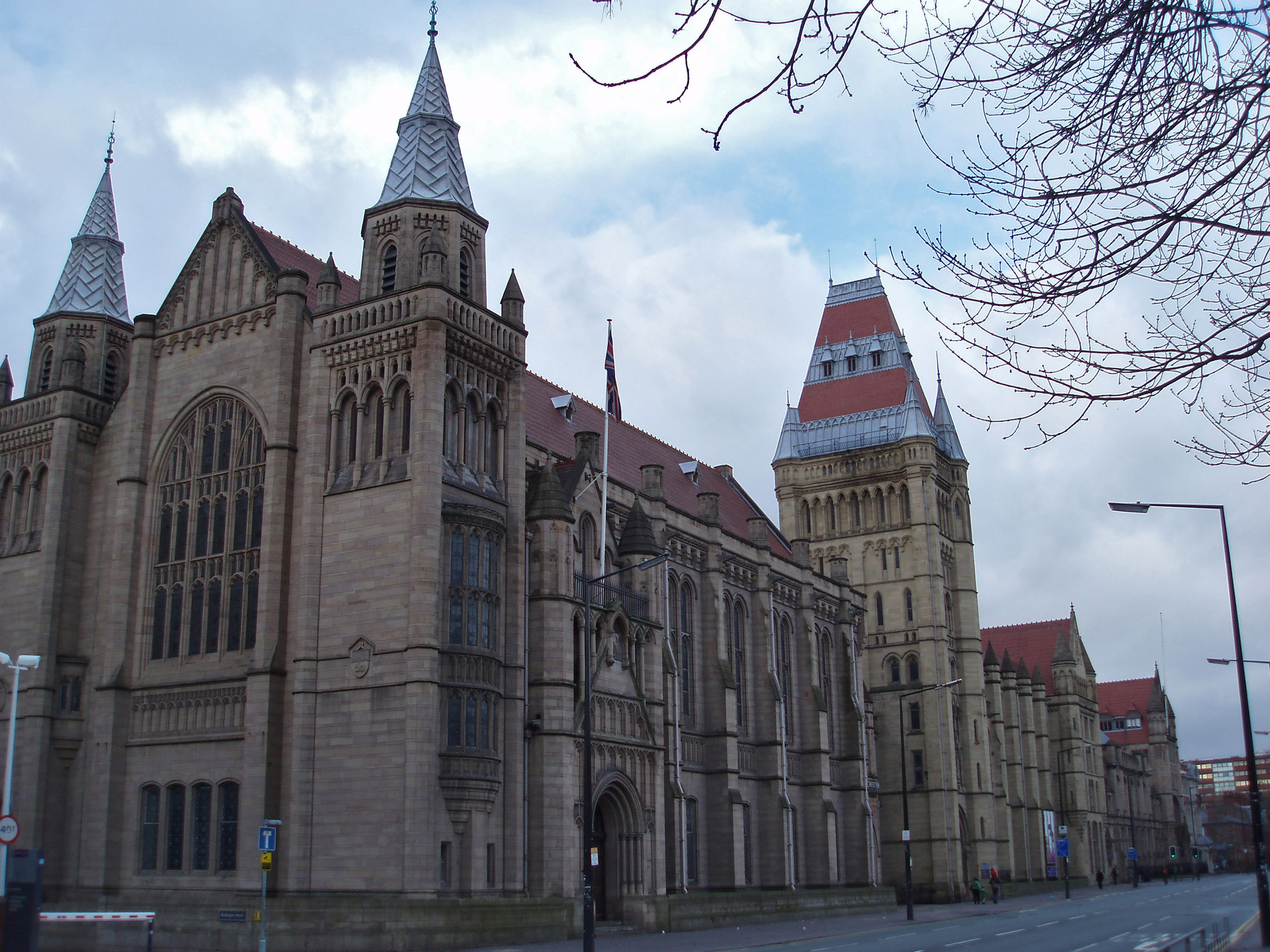
Hawkins\Brown have offices in Manchester and London employing some 240 architects. Current projects include the London Crossrail development and the Schuster Annexe at The University of Manchester (render shown above).
Many Thanks to Jack Stewart & Harbinder Singh Birdi & to Laura Keay & Jake Stephenson for inviting us to present.
For More information visit: http://www.hawkinsbrown.com/
Scott Miller, B.15 Modelmaking Workshop 2017


