Materials Recycling, Saving the World! (and yourself some money!)

One of the most important habits we can pick up as designers and makers is to make the most efficient use of anything that is freely available to us. It is essential that we consider the conservation of materials and the reduction of waste from our projects in order to play our part in maintaining a broader sustainability for the future. The least we can do is to efficiently plan how best to use the material we are working with.

This can be seen as a hindrance to quickly starting a project but in reality, effective planning can help reveal more appropriate materials for a particular task as well as best use of those at hand. This saves money and expands our understanding of material qualities.

Before planning based on an infinite amount of material it’s good practice to break down your projects into components as a list or drawing which can be referred to when assigning materials. With this reference at hand we can decide on the most appropriate materials for each component or group of components.

An example of this might be all ‘green’ or natural areas of a site could be represented using timber against a coloured acrylic as the man made roadways. Knowing this we could separate those components and begin collecting materials that suit the required sizes.

Material Saving 2

Looking through off-cuts left from past projects it is likely you can produce much, if not all of your model for free by using these.

Using Sheet Material for Component Layouts

By working out what you need from a particular piece of material before you begin to cut you can get the most from each piece you use – off cut or new.

Material Saving

This applies to both hand drawn and CAD drawn components. Rather than placing components scattered around a sheet, tessellate and arrange them in a manner that gets the most out of each piece (See Screen Shot above for a good example).

This example from Abhi Chauhan’s project below demonstrates how a piece of laser cut MDF with effective component arrangement can get the most out of a sheet of material.

DSC03077

Re-Use of materials and model components


Before you decide to use new materials you can also look at the role of your existing works and rework them into new ideas as demonstrated in this student video made by Signe Perkone and Sigita Zigure who graduated BA Architecture last year. Whilst we are keen to record all work produced it is impossible for us to keep everything so by re-using models this way we are helping to do our bit to reduce waste.

Scott

‘Testing The Machines Of A Third Industrial Revolution’ Cross Section Presentation Model, Abhi Chauhan

Abhi (33)

This project was completed in the final weeks of the last academic year by 6th year MA Student Abhi Chauhan. The project is the follow on to the 1:100 section we featured several months back. What is particularly appropriate about the styling of this project is the subject matter or the site. Being a 3D Printing Manufacturing facility of the future means no better method of production that the technology in question. This is definitely something to consider when devoting yourself to a major project like this – for example, if you are building an eco-concious design then that ethic should carry through to your presentation and thus model construction. This project sticks to its purpose through and through.

Abhi has been since graduated and started a full time position at Grimshaws in London. We wish him all the best in his future career!

IMG_4753

This piece will be on display as part of our B.15:45 Exhibition so be sure to have a look in person.

Abhi has kindly written us this extensive account of the theory and construction methods he used in this stunning final piece. Enjoy!

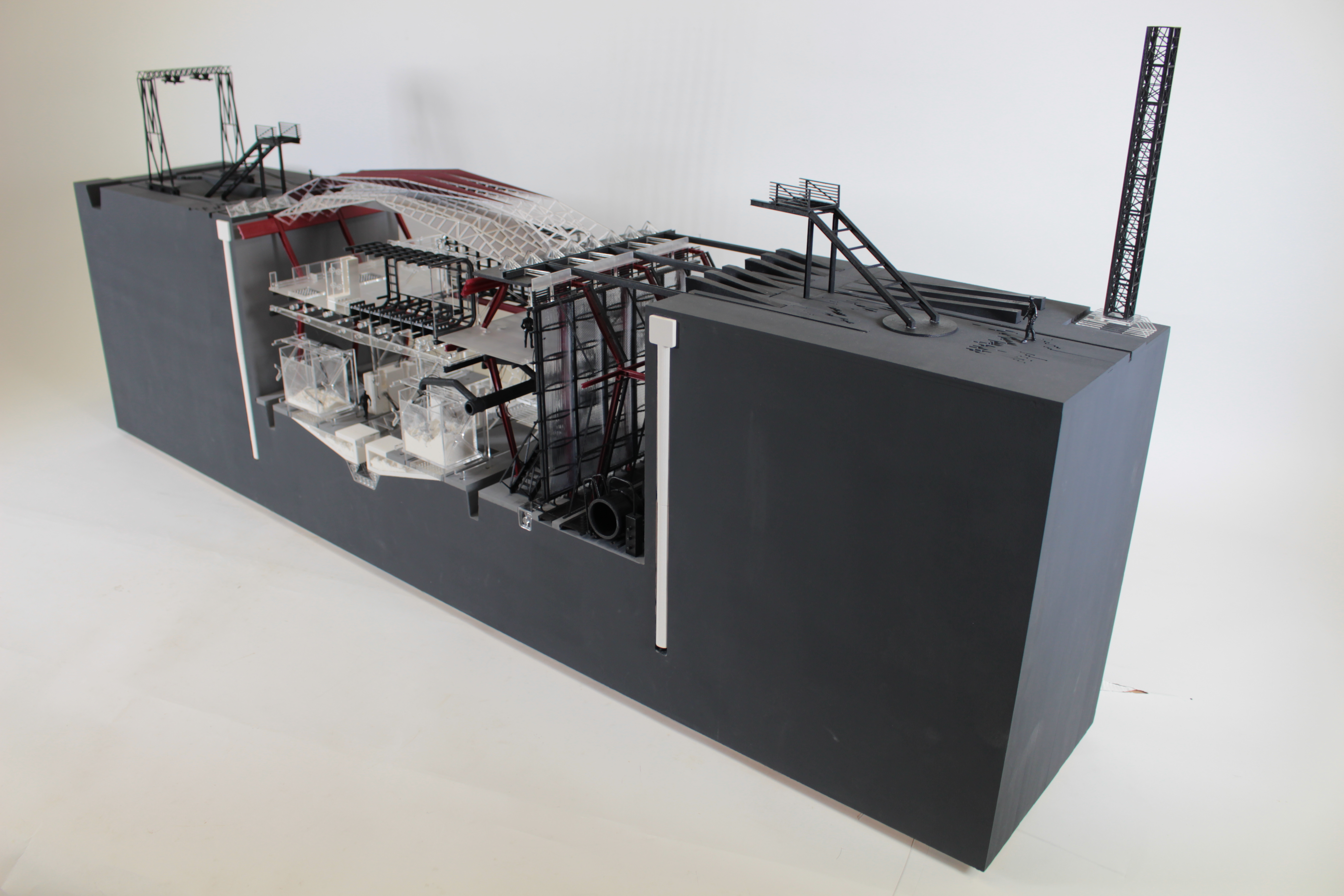
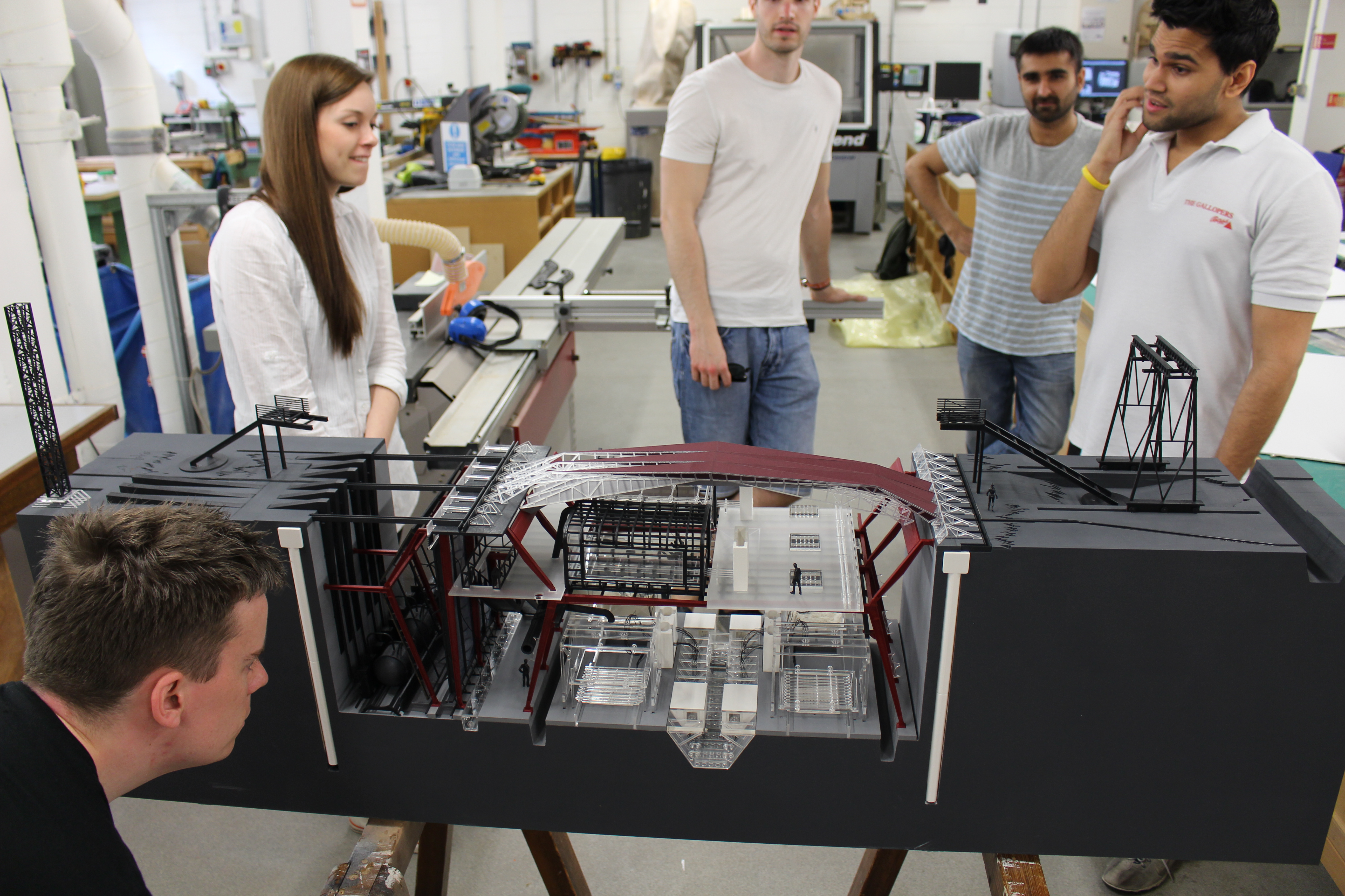
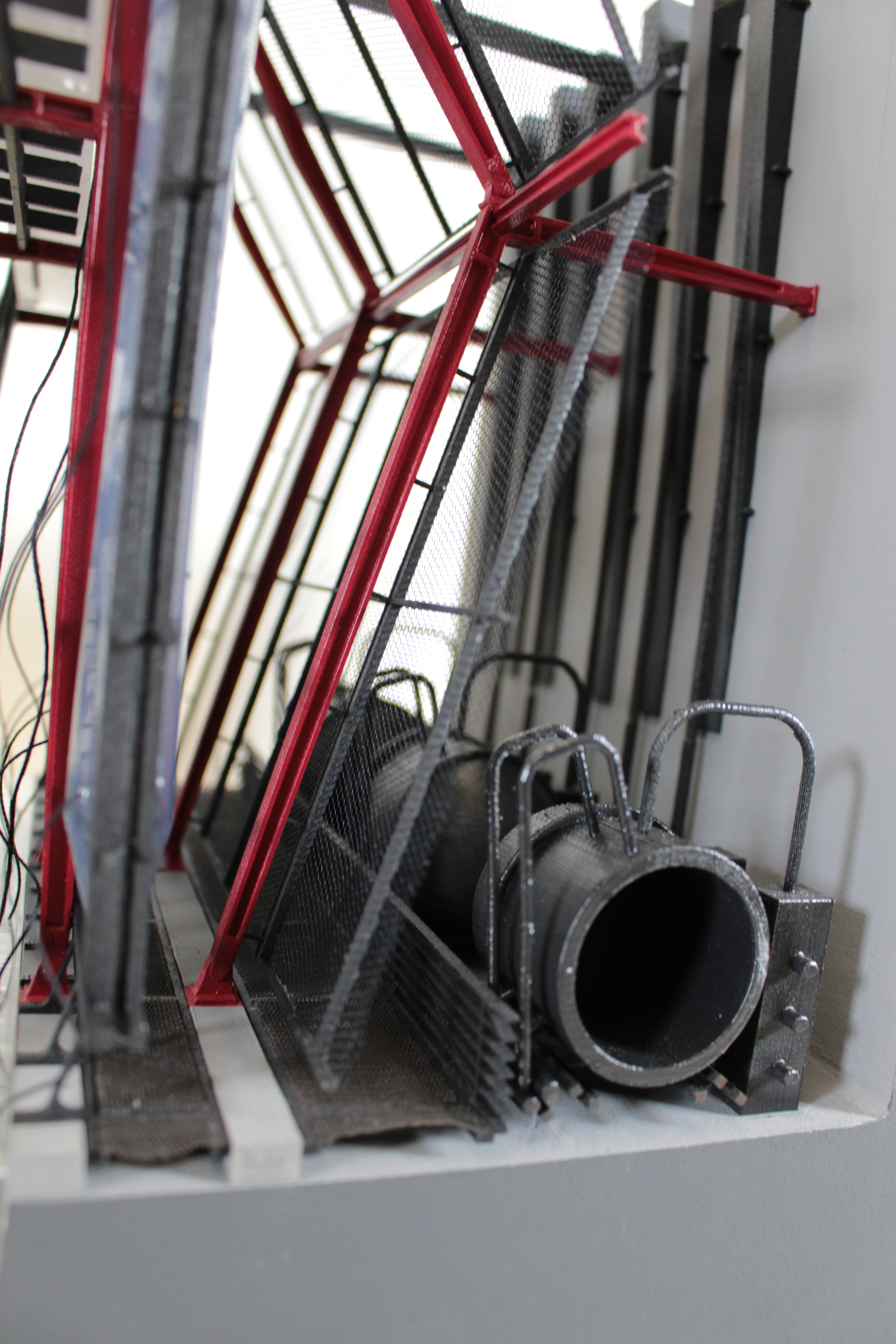
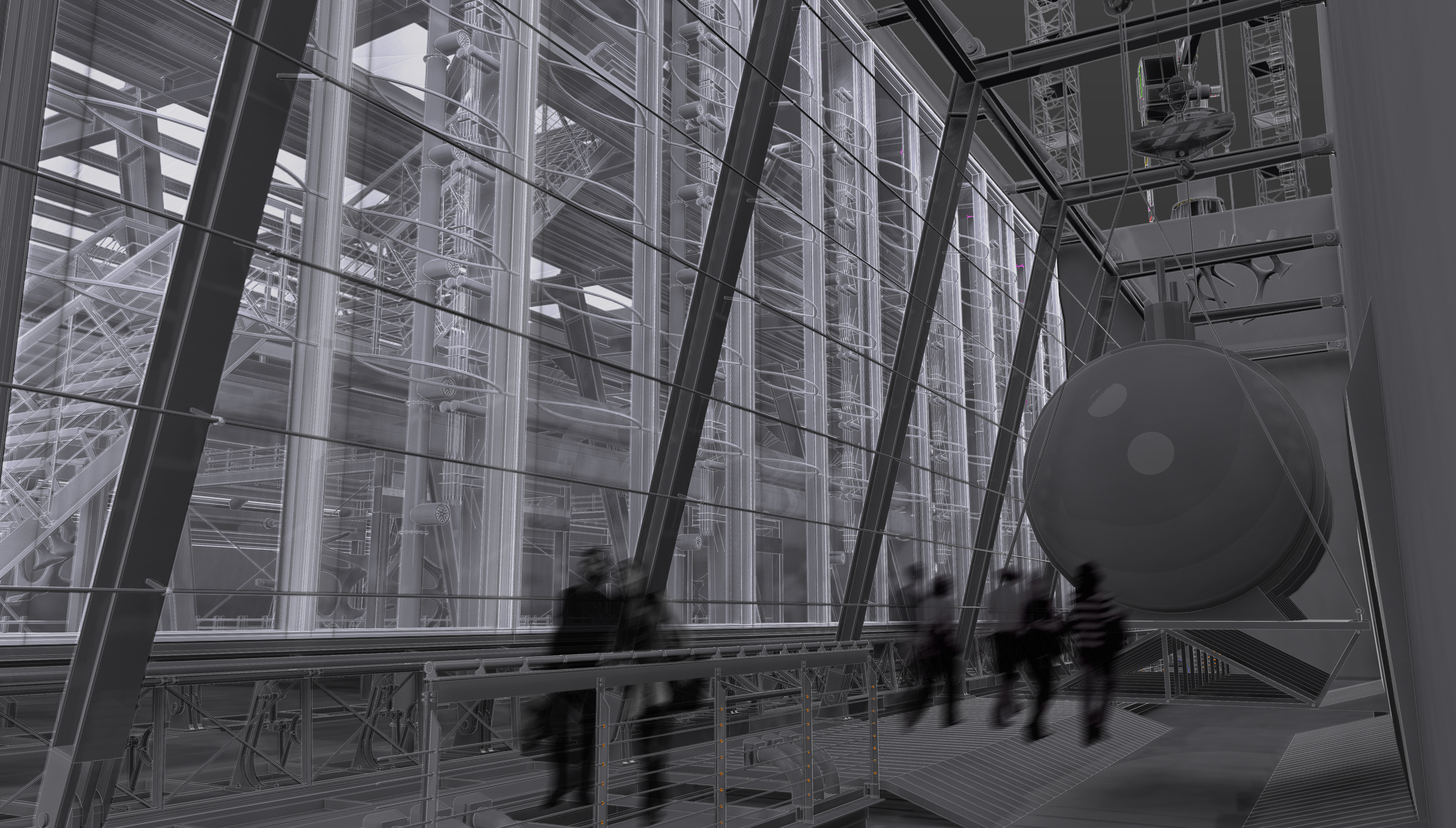
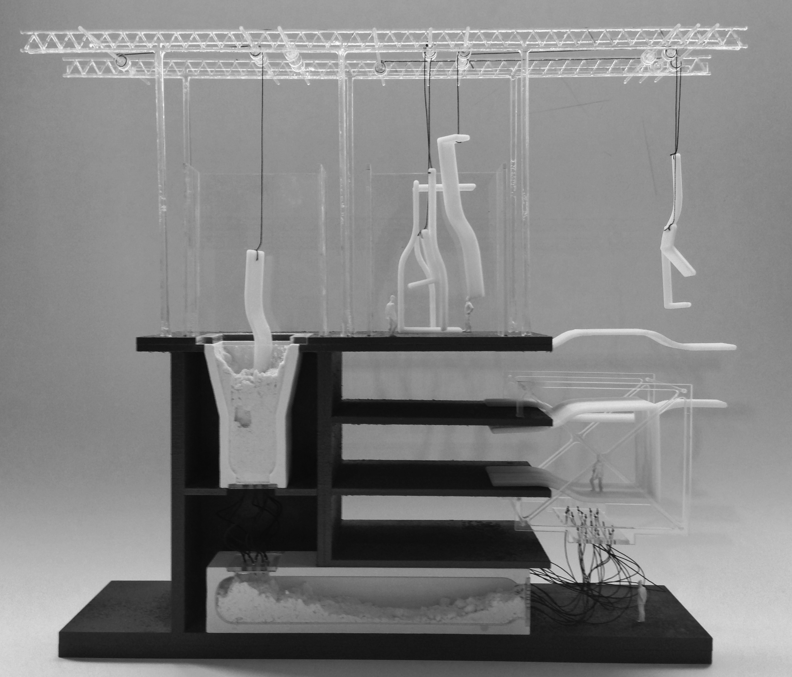
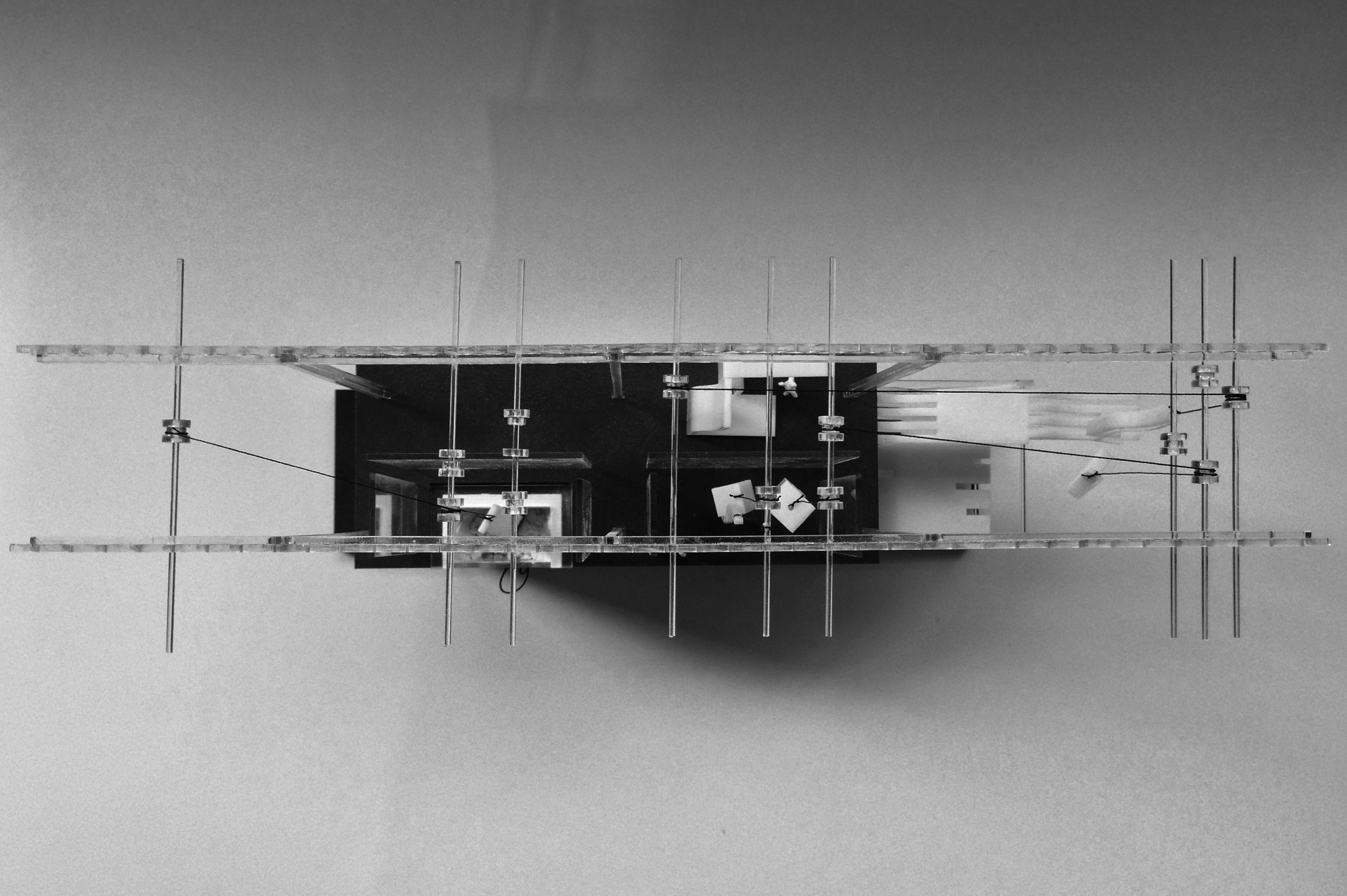
This model is a final exhibition 1:50 sectional model. The slice is located through a key component of the building scheme titled ‘The Machines Of A Third Industrial Revolution’ The model slice – in detail depicts the processes of 3d printing of 1:1 architectural components, to be tested on a stalled concrete frame bounding the site. The design of the facility is such that it sits into a trench in the ground and features a folded roof structure which integrates a 3d printed park at ground level with the industrial processes of the facility within. The scale of the facility has been designed to be oversized, to deal with the variety of large scales that are needed in the manufacture of components for the construction industry.

The model builds upon the 1:100 sectional model completed earlier this year, and takes on a similar aesthetic to that of a cross section through a large industrial machine hanging of the walls of the facility.

The model has been constructed with a variety of different techniques.

IMG_1003

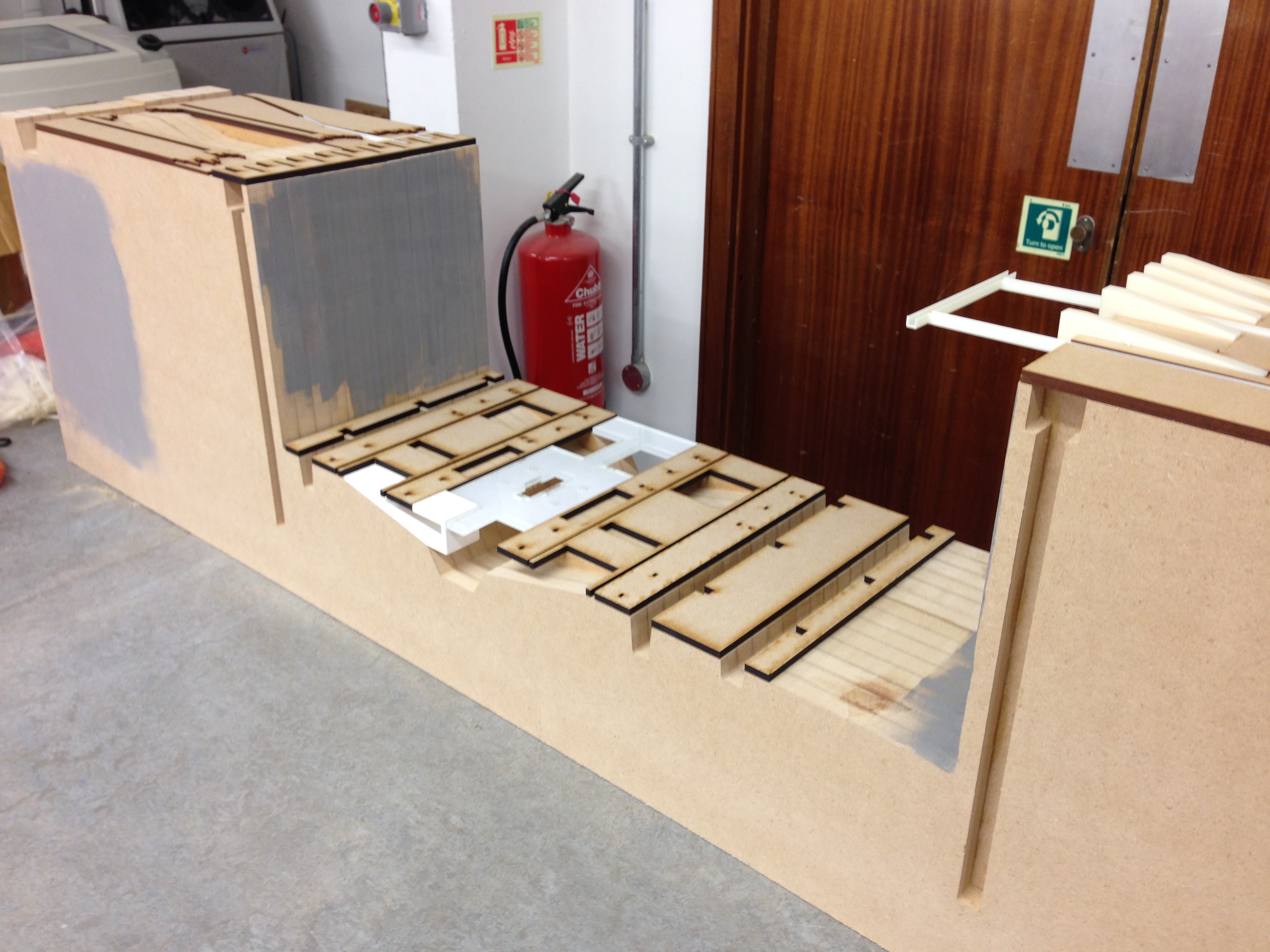
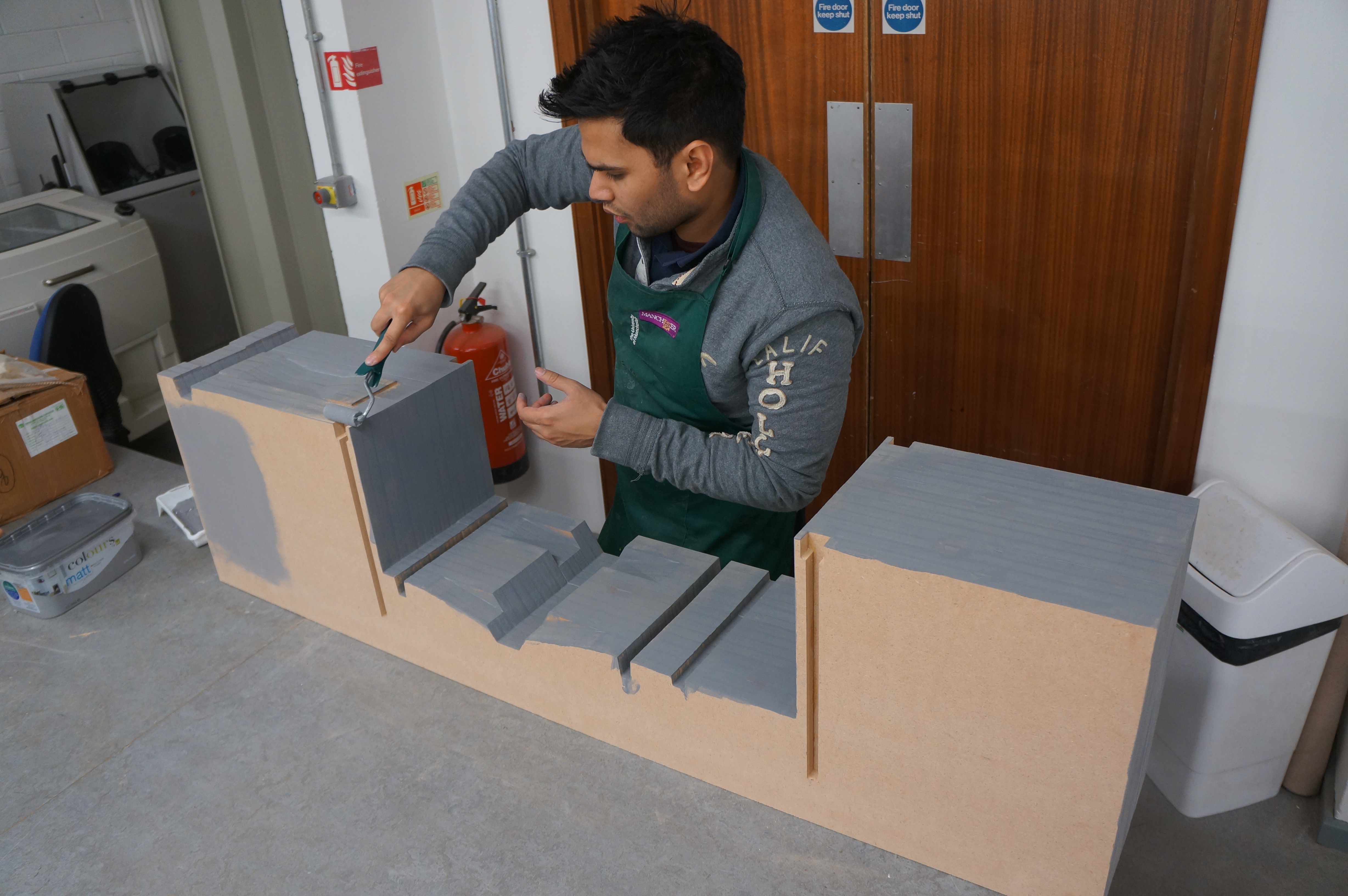
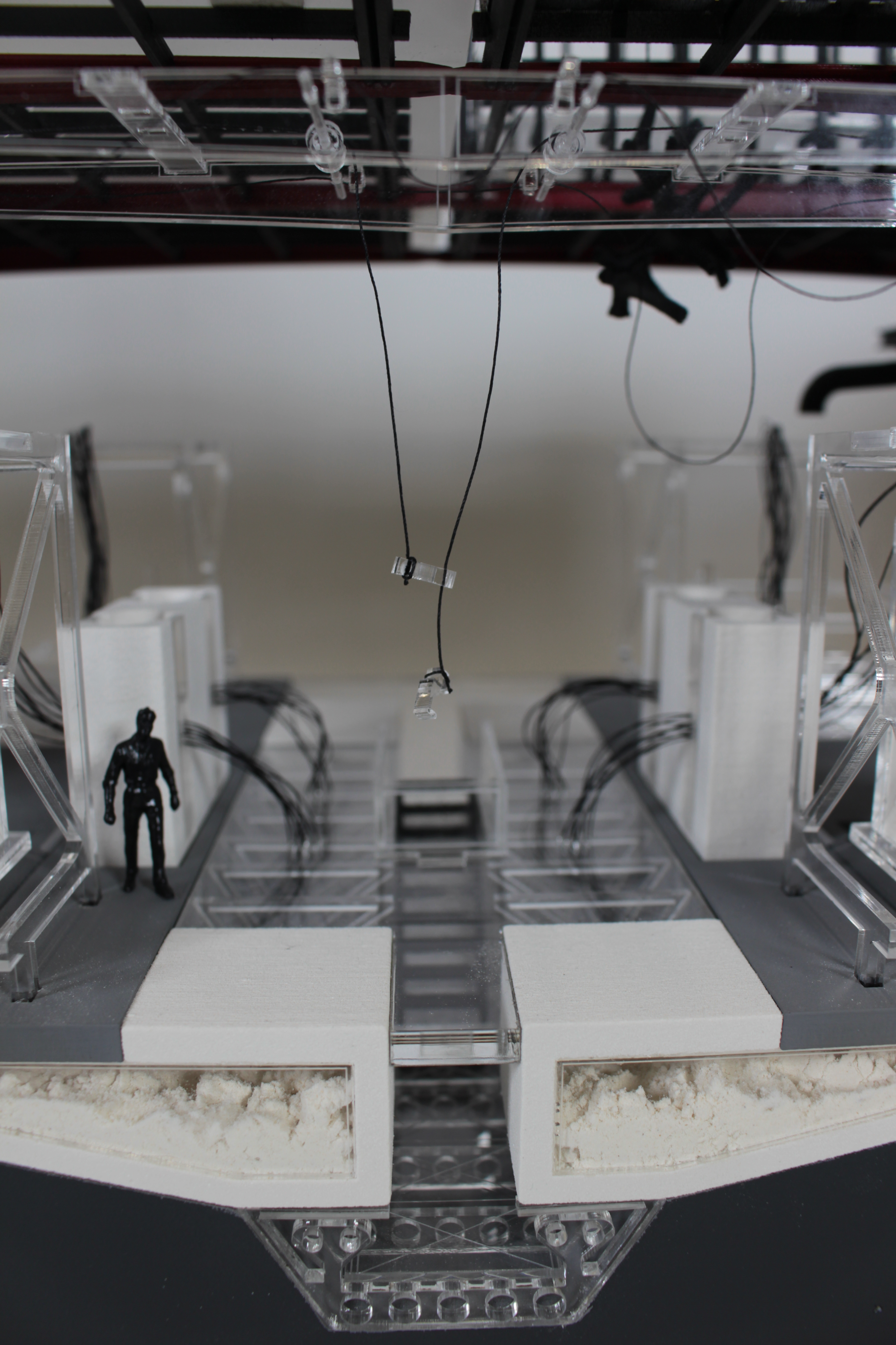
The base has been CNC cut from x15 18mm mdf sheets layered and glued together. This method, although not the most cost effective meant that each layer of the base could be designed to incorporate slots and grooves within for housing of the various components that would eventually complete the model.

Abi (10)

2

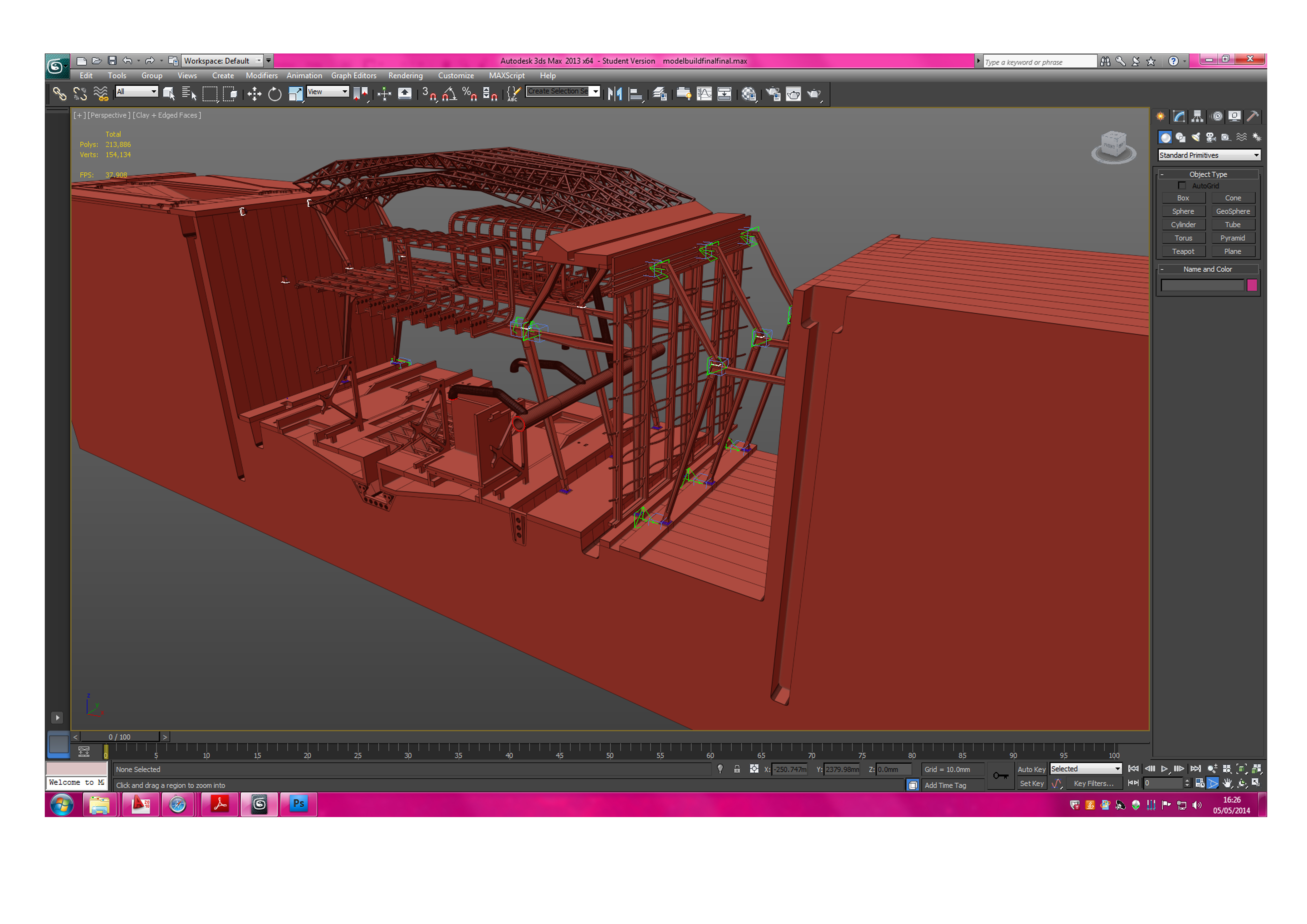
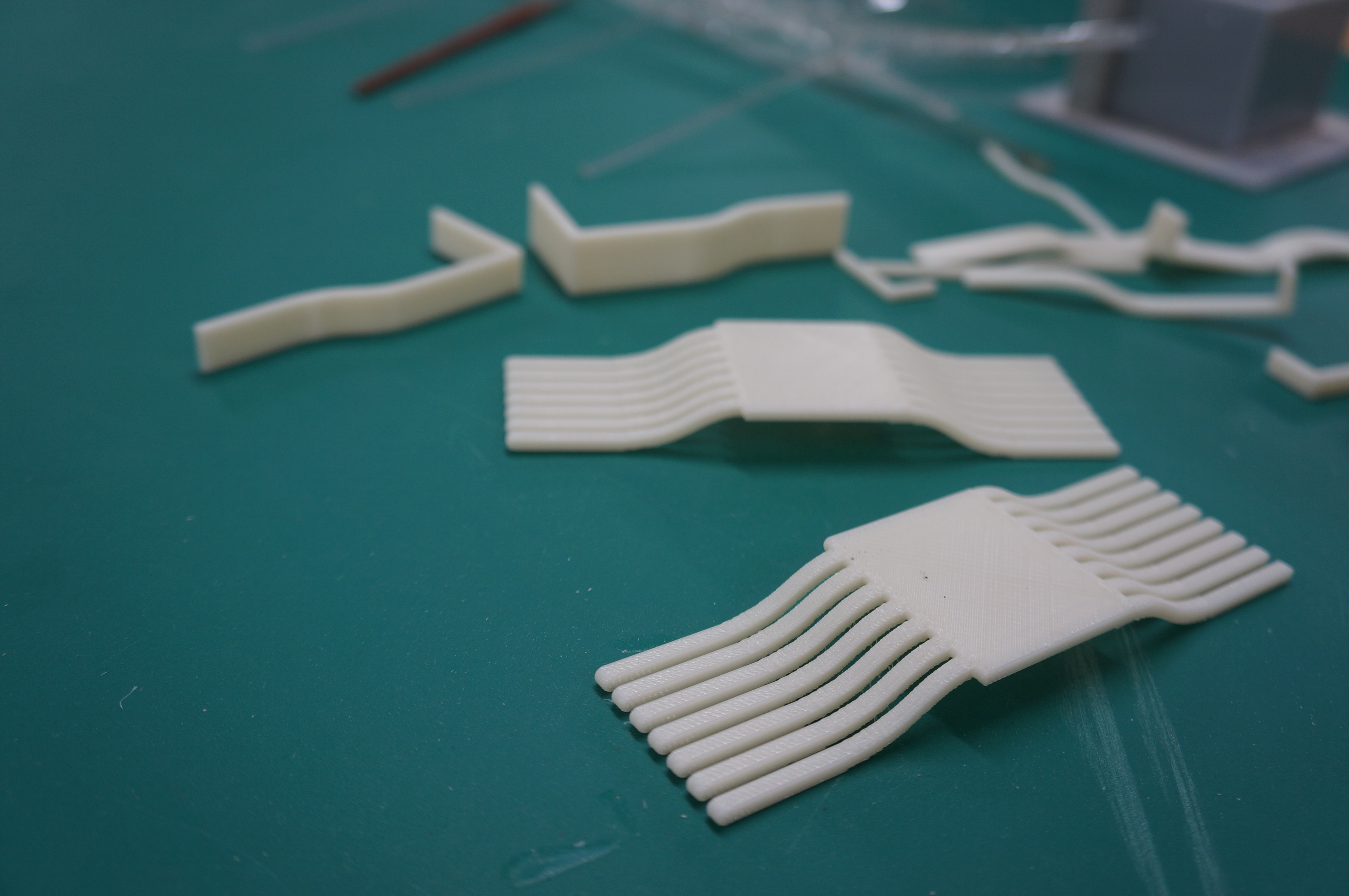
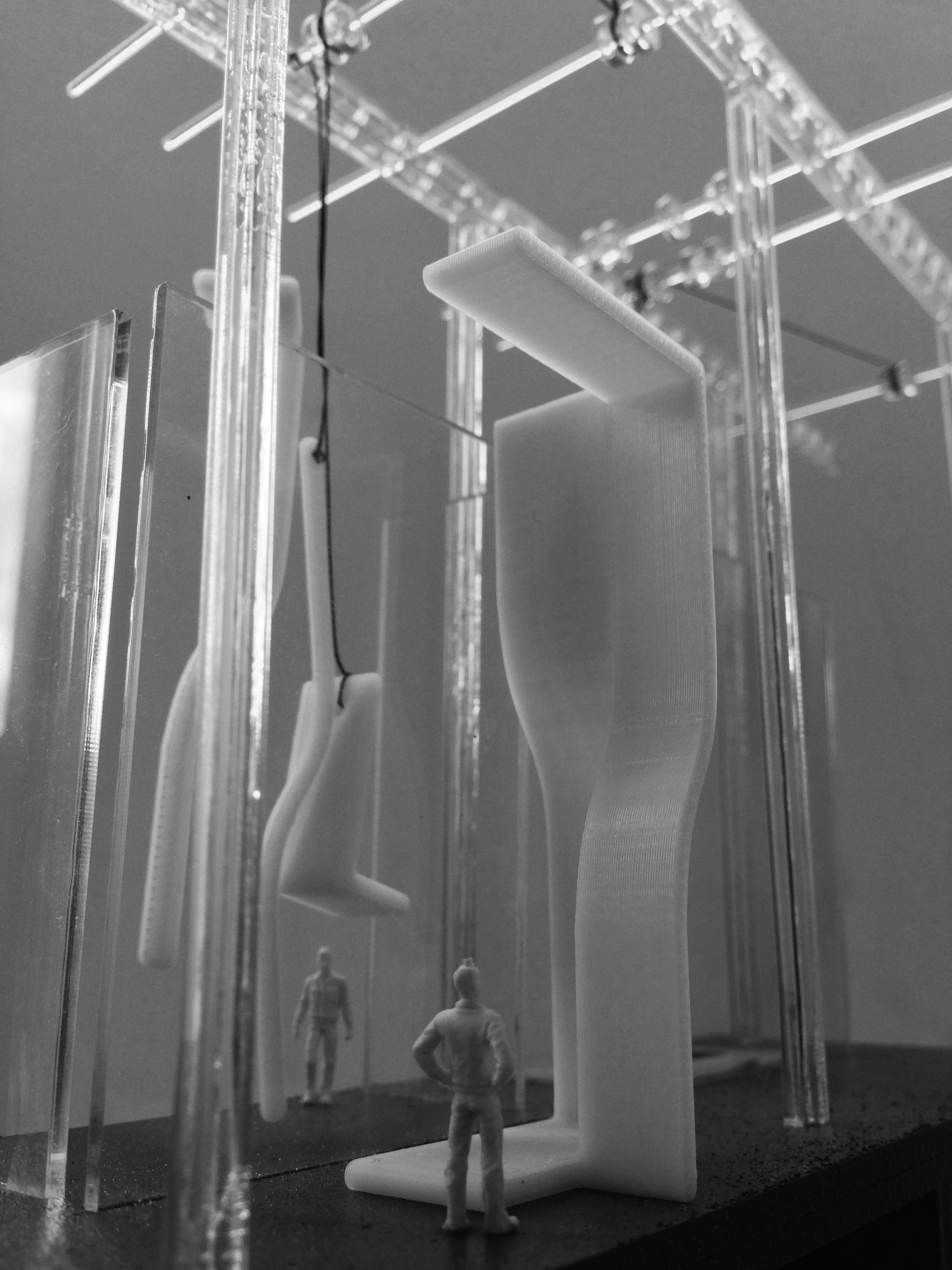
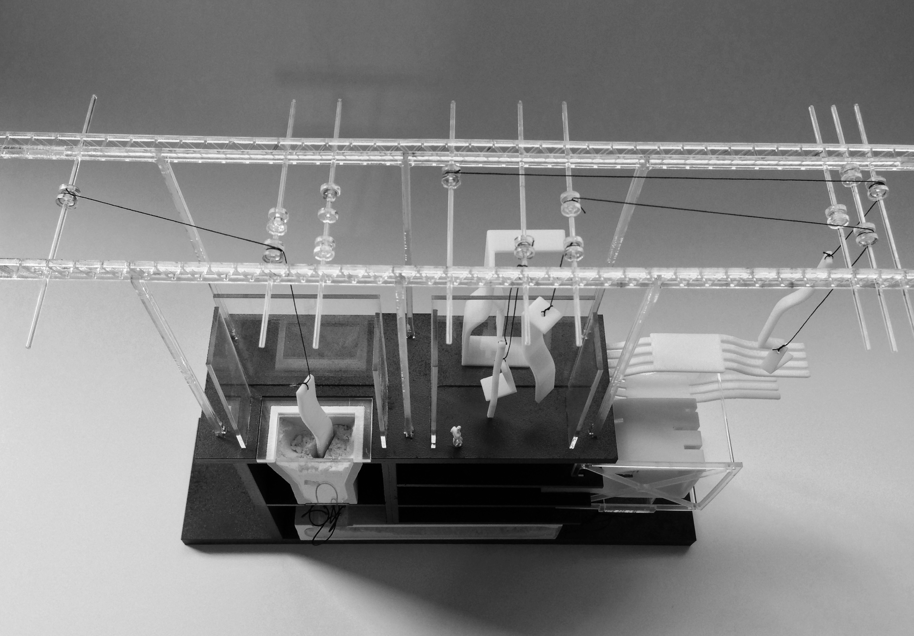
The red structural parts forming the portal steel frame structure hung within the trench were all constructed in 3ds max and then 3d printed on the ABS printer. These parts were then spray-painted to get the final red finish seen. Other components that were printed, include some of the facade components, and the series of storage tanks and pipes to the right of the trench. This method of manufacture was chosen sue to the time constraints, the subject matter of the project, and the complex shape of some of the parts.

IMG_1016

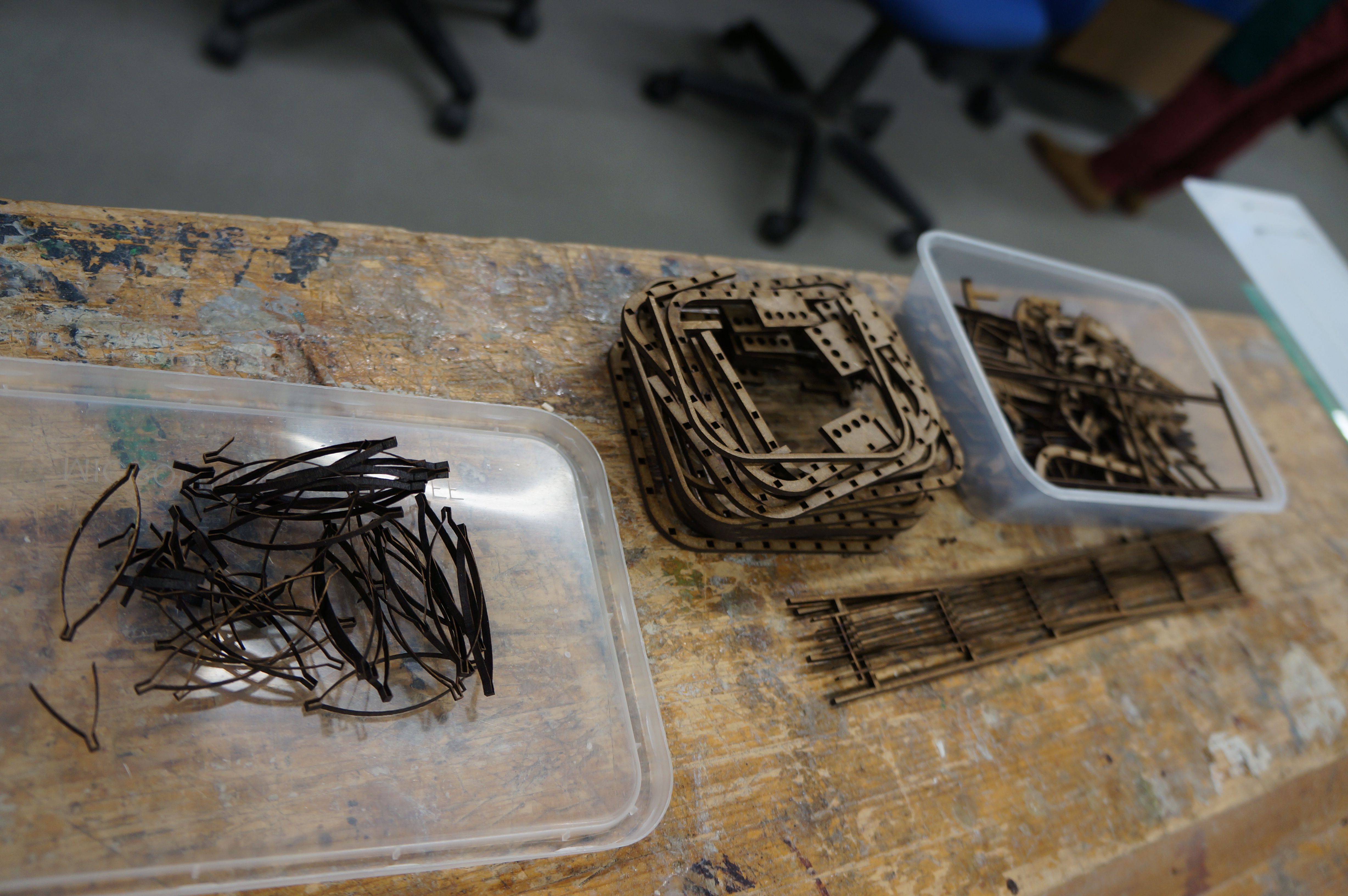
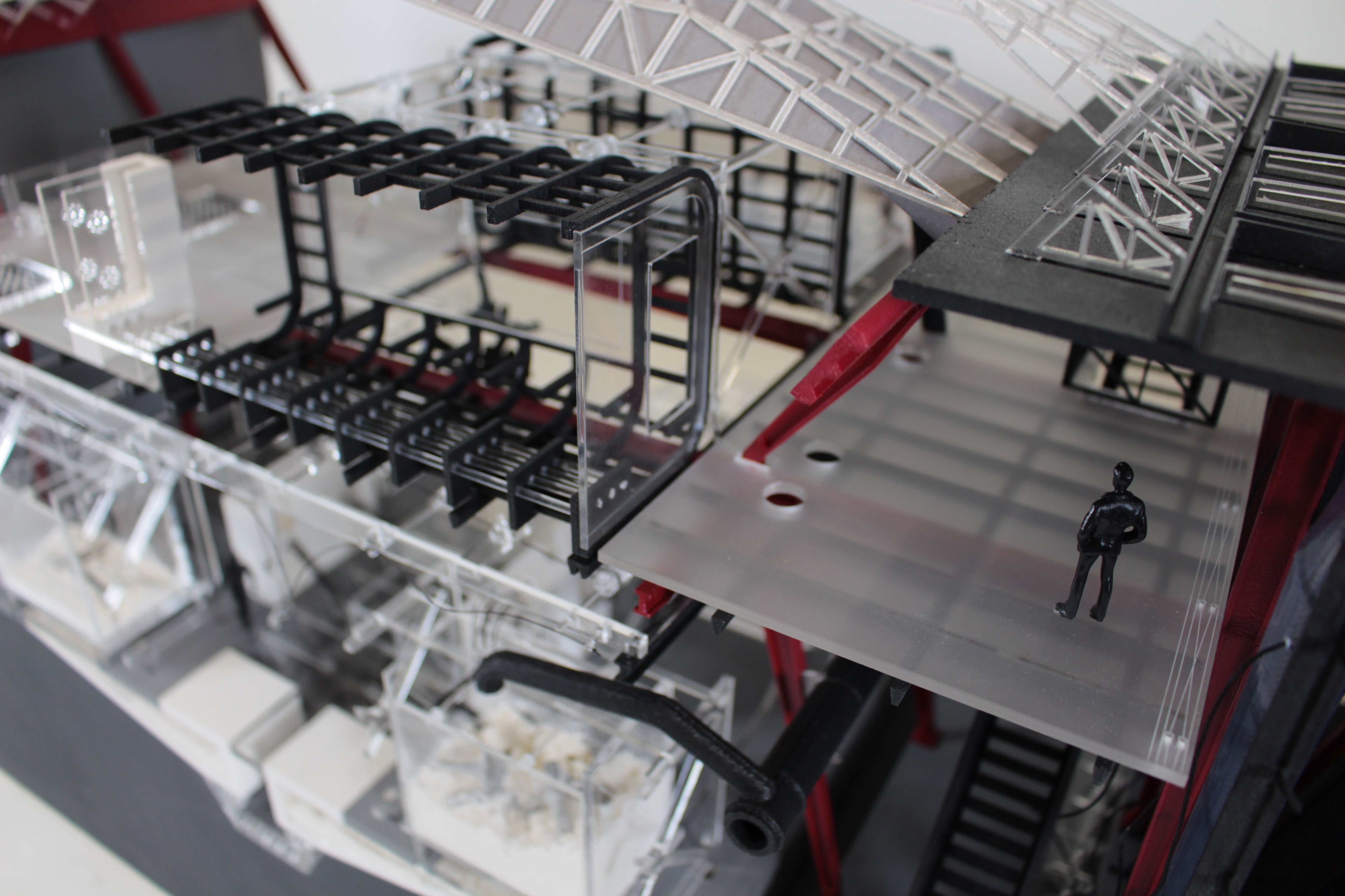
The roof was also 3d printed and a shelling script in grasshopper gave the folded structure a thickness to make watertight for 3d printing. This part was the most challenging to construct and after a variety of failed tests the part was printed at Hobs due to their larger printer beds (up to 1500mm wide) which allowed for the part to be printed as one component. Finishing the roof are a series of card panels (depicting a metal skin) which were laser cut and engraved. These were bonded to the 3d printed structural roof frame using spray mount.

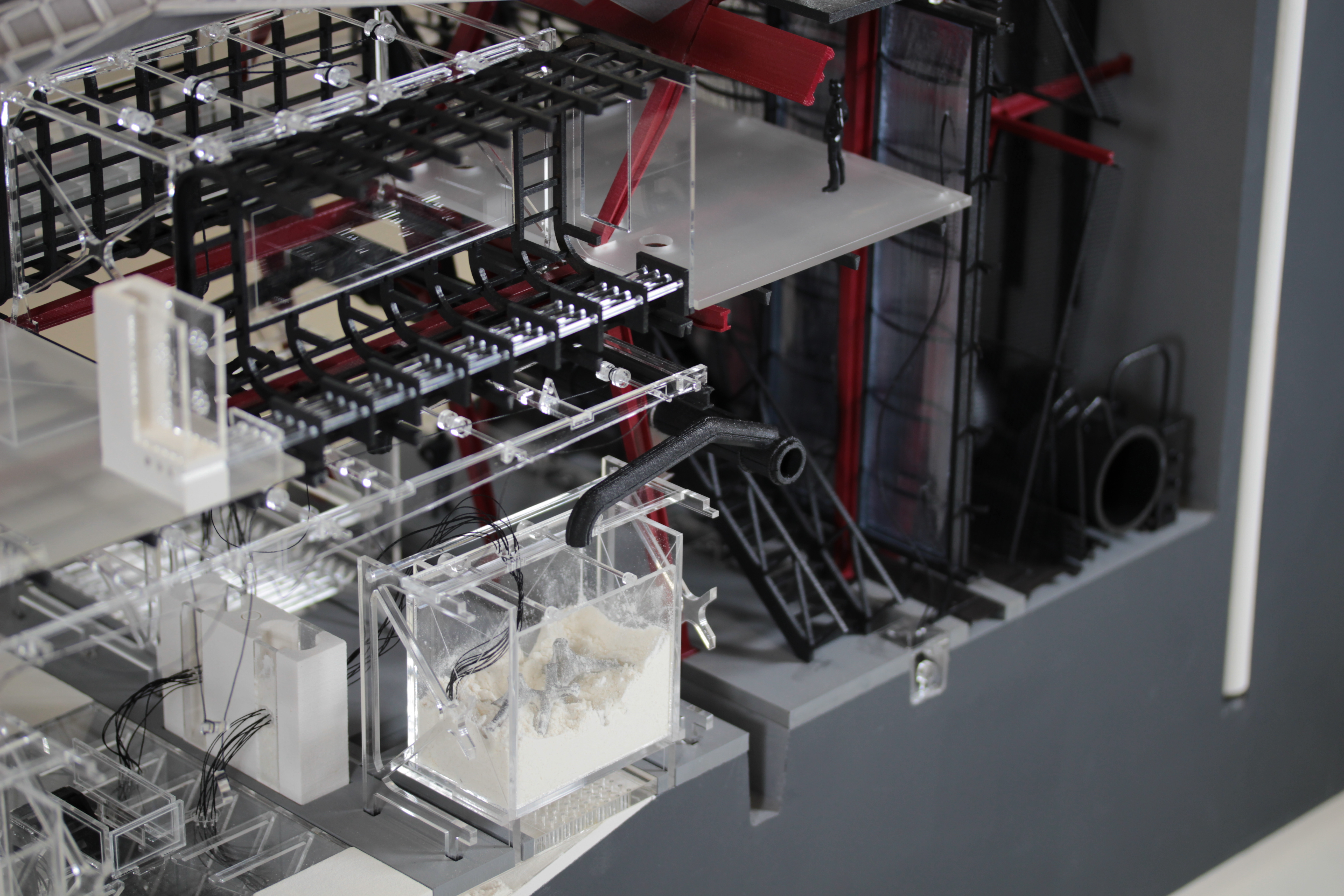
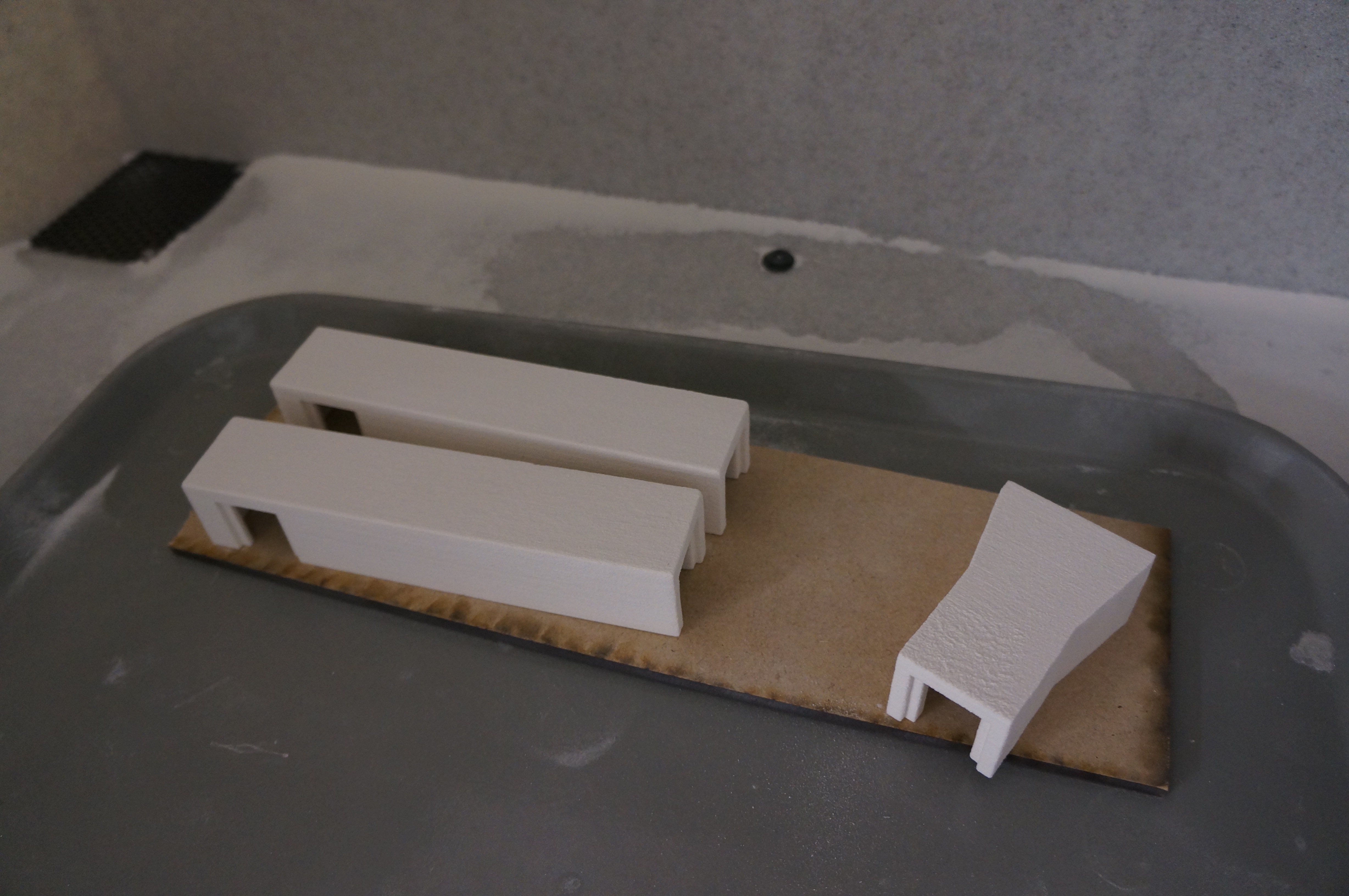
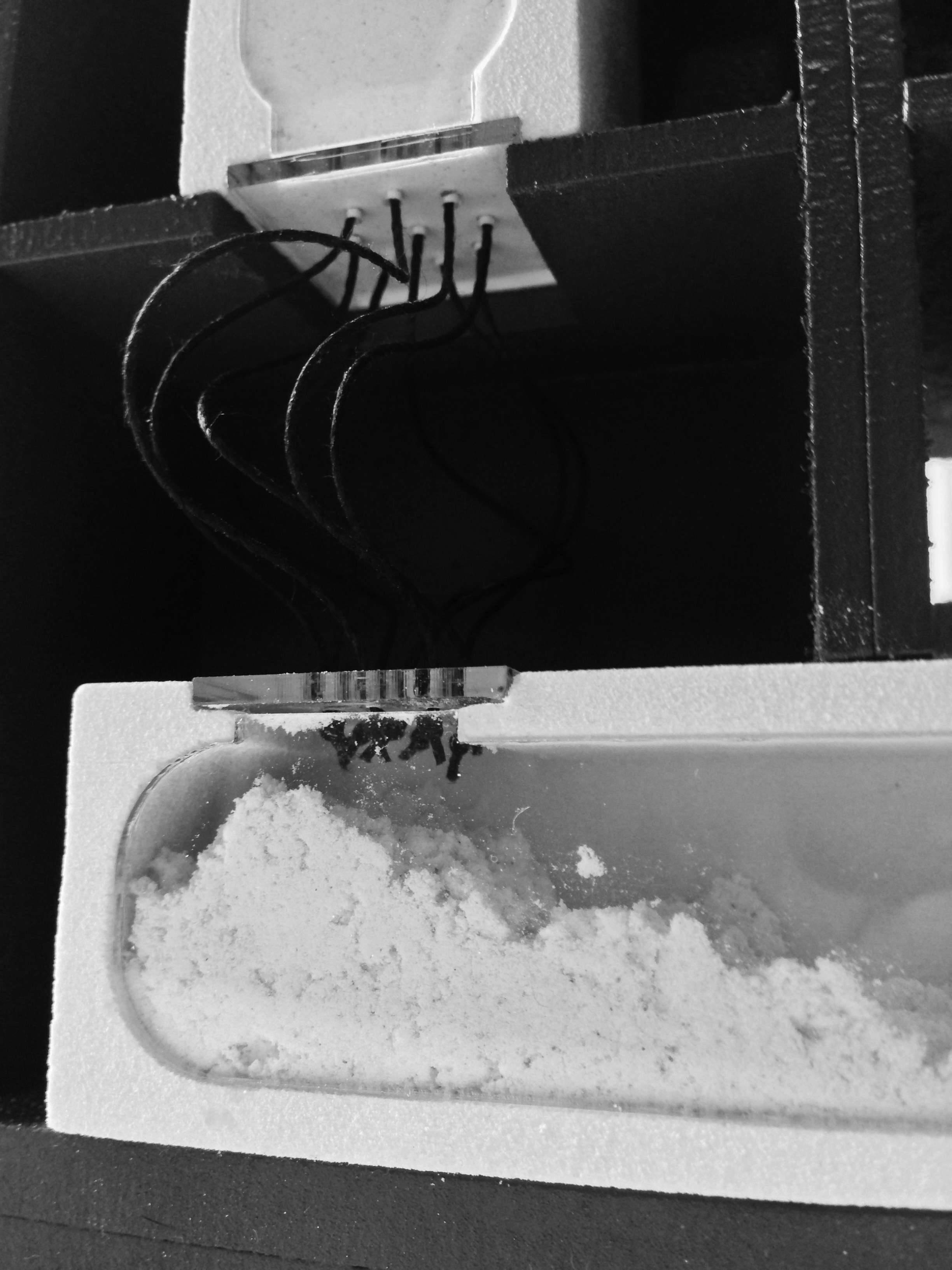
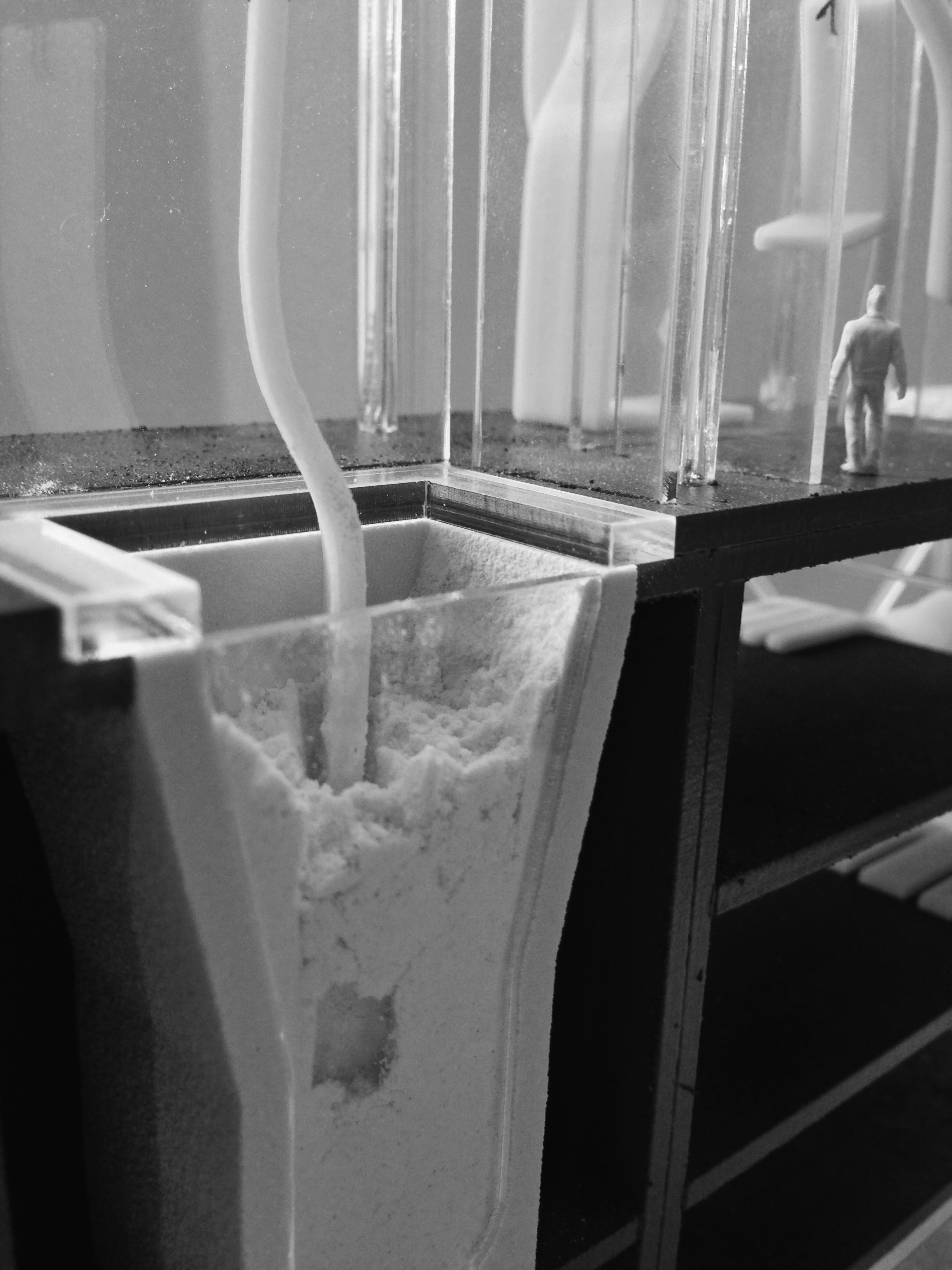
The material archives (in white) set into the base of the model were the last parts to be 3d printed on the model, and were done on the powder 3d printers. These constructs were notoriously fragile and once installed in the base had their edges and portions of their rebuilt in white pollyfilla.

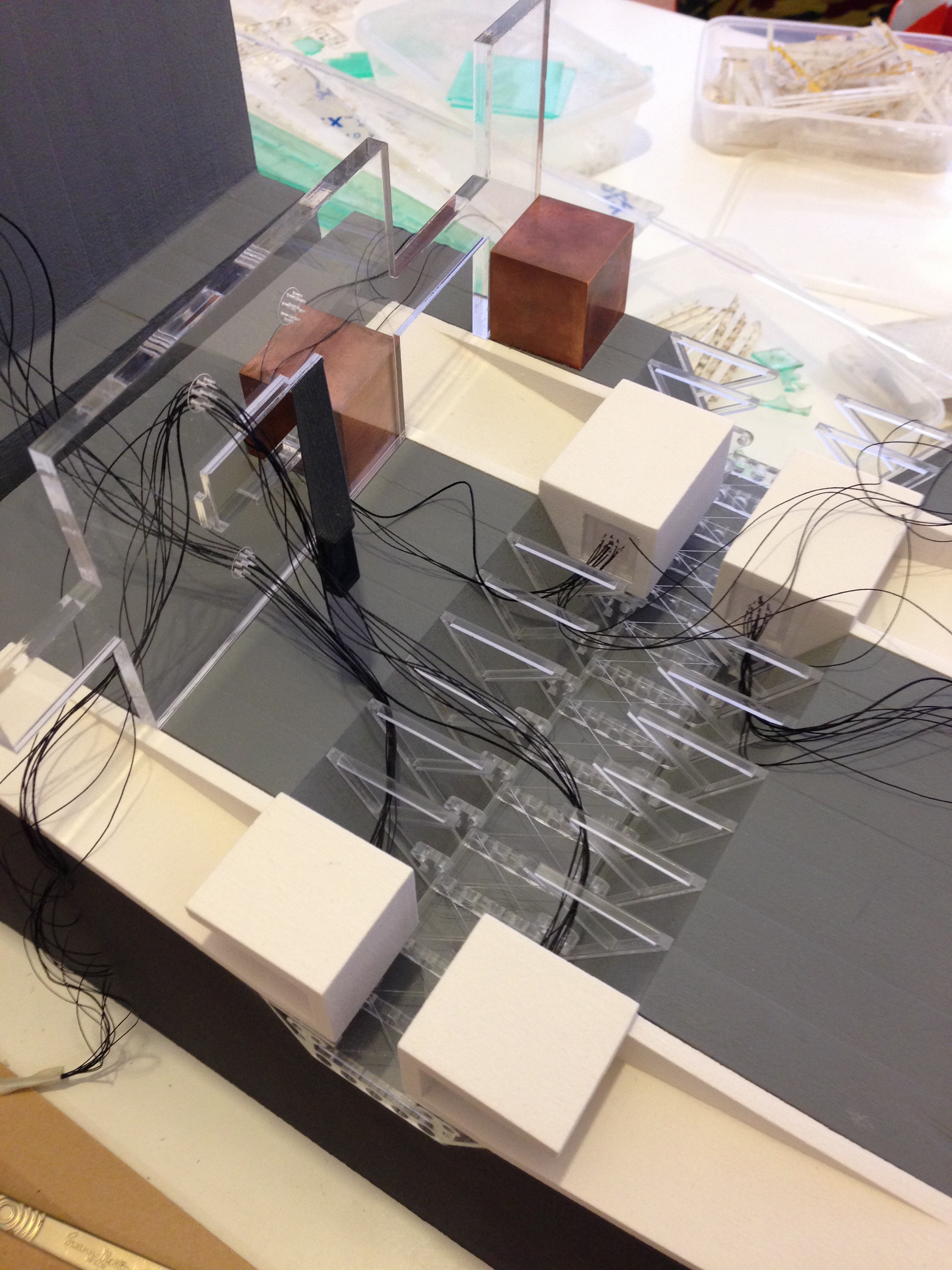
The remaining components making up the model have been formed from either 2 or 3mm clear acyclic. For example the 3d printers on the -2 level have been laser cut form a mixture of 2 and 3mm acrylic and then assembled to snap fit and slot together to avoid gluing. This clear aesthetic was chosen for a variety of the model parts as can be seen.

Abhi Components

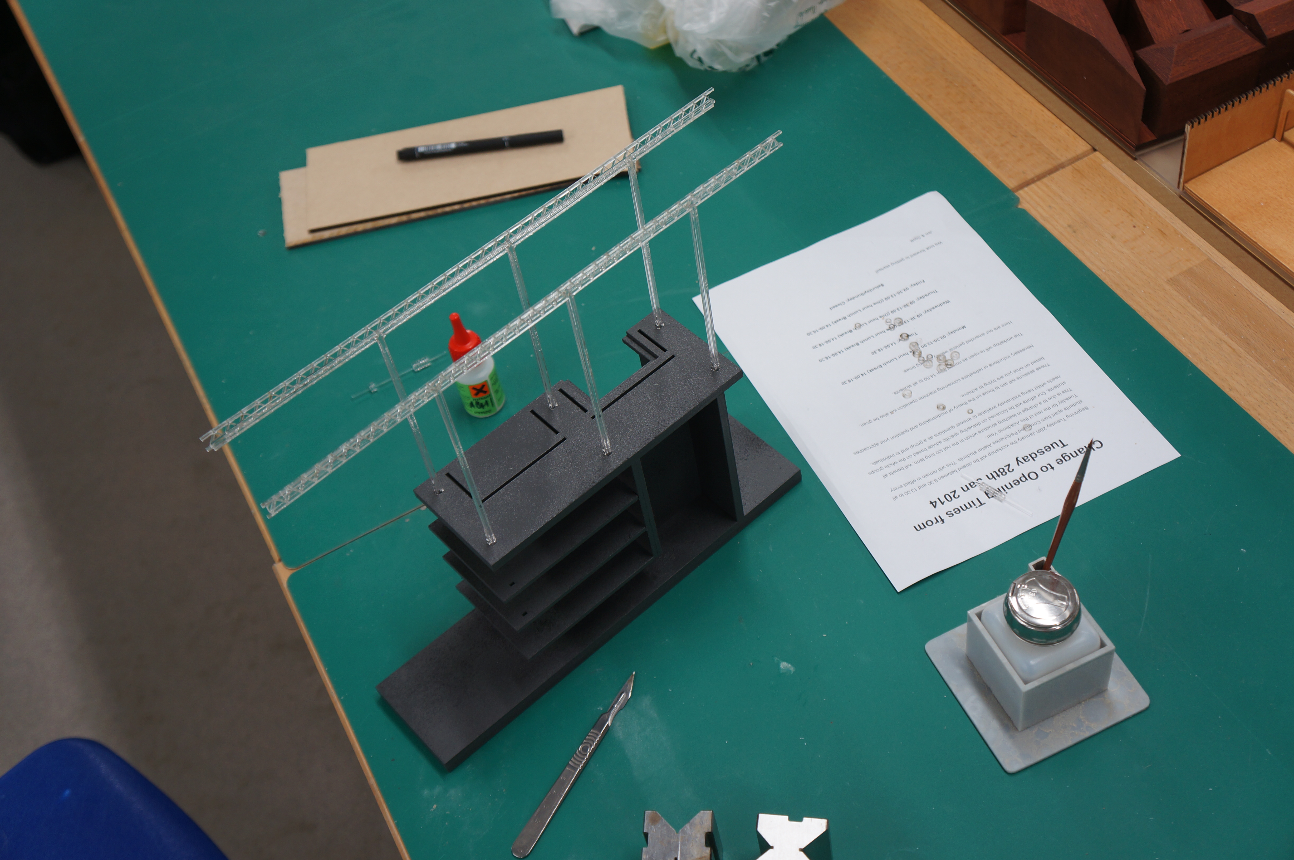
The landscaped elements including the cranes and gantry and the main internal staircase were all laser cut from 2mm mdf. These part were all spray painted to the final grey and black finish shown.

The facade skin (resembling an ETFE system) was vacuum formed over a 3d printed mould. The mould was designed with groves in it and as such were expressed in the final plastic shells.

Before any parts were manufactured every part was modelled in 3d and then assembled to create a master digital model. (see image) Due to the large amount of parts on this model this was necessary to eliminate any unforeseen mistakes which would be harder to rectify once parts had already been cut.

IMG_1046

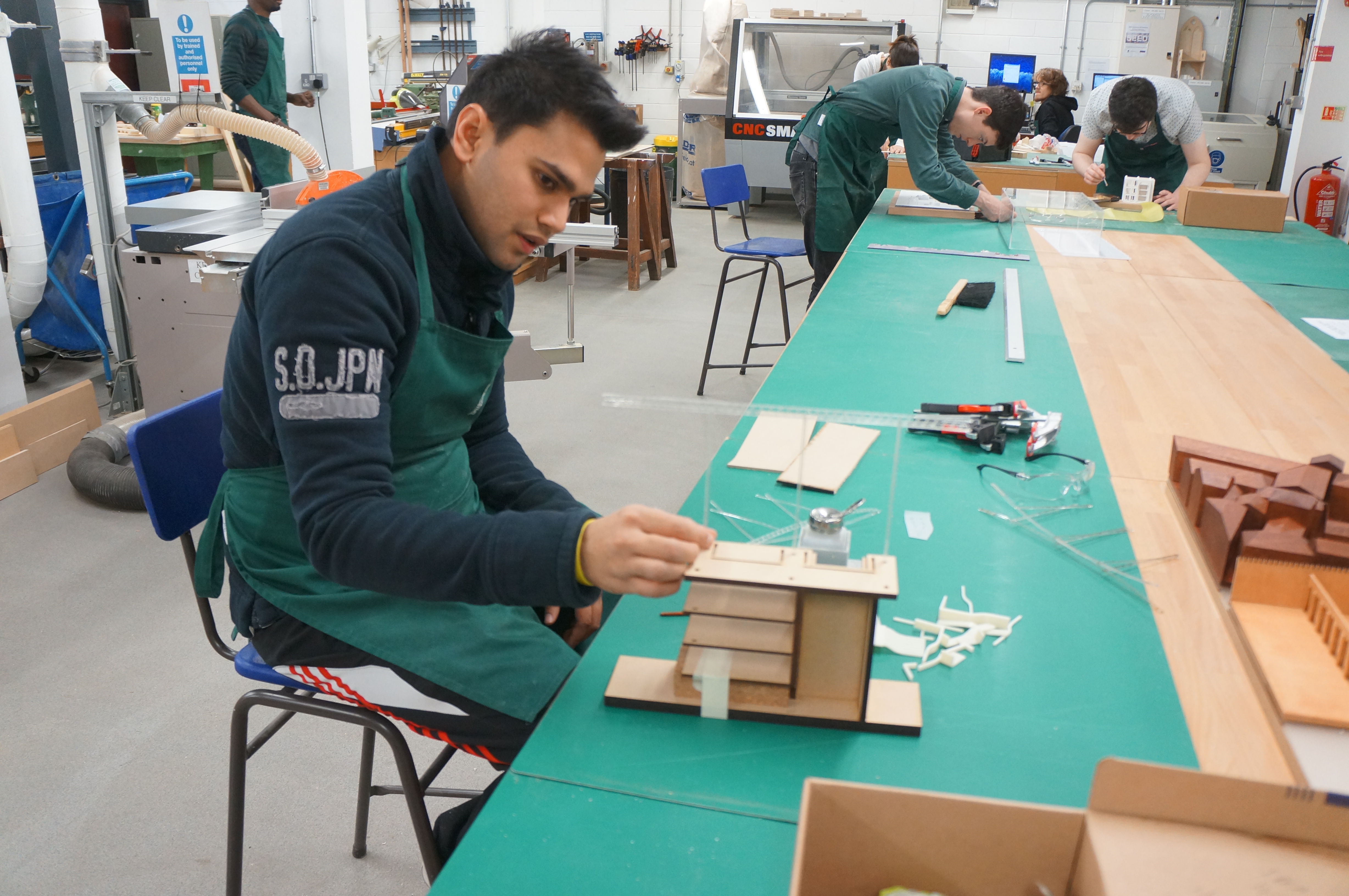
Each part of the model was treated as a mini project i.e. the main facade, the main stair case, the 3d printers on the ground floor, etc. Once these were all assembled and sprayed the whole model was put together like a giant jigsaw. Due to the fact that almost every part was digitally fabricated there were few tolerance errors during final assembly.

The model took approximately 3 weeks to translate from an actual section into model drawings and then 3 weeks to get all the parts cut and painted and a final week to assemble together.

Abhi (6) Abhi (49)

Abhi (55) Abhi (2) Abhi (66)


Abhi Chauhan: ‘Testing the Machines of a Third Industrial Revolution’ 1:100 Site Section Model

6th Year MArch student Abhi Chauhan has recently completed several models as part of his Intimate Cities project. The earlier models were used to demonstrate initial concept ideas and helped influence design changes. In keeping with the subject matter of the proposed development Abhi has put heavy emphasis on digital manufacture.

Abhi gives us an over view of the project and how this model fit in to its development:

As part of the Intimate Cities Atelier this year we were concerned stalled construction sites in the city of Manchester. These sites are unique in that their infrastructural order has been partially installed and my primary aim is the reconnection of these sites back to the city context. Situated on the Potato Wharf stalled construction site, the final scheme looks at the idea of bringing around a Third Industrial Revolution, by looking at the research and testing of an advanced manufacturing technique (3d printing) and a new energy infrastructure, (hydrogen fuel cells).

 Realised as a masterplanning strategy the stalled concrete frame on the Potato Wharf site is used a ‘live’ test-bed for 3d printed architectural components, in addition to this the scheme engages with the redundant  transport infrastructure bounding the site and reinstates the canal and rail network as a distribution matrix for the transport of raw material. A reconfigurable 3d printed public park defines the edges of the new site in the overall strategy.

VISUAL LIGHT

The renders depict how the main 3d printing manufacturing hall and hydrogen exchange will look. The 3d printing facility is concerned with the research, manufacture and testing of 3d printed architectural components and as such the construction and detail is oversized to deal with a variety of different scales present on this project.

This first conceptual model depicts the main processes occurring in the 3d printing facility and follows the life-cycle of a 3d printed architectural component from its raw powdered state – stored in a material archive; to the printer beds; then for reconfiguration in a graveyard of failed components; and ultimately to its reverse engineering back to its raw powdered state.

The main frame was laser cut from 6mm MDF and designed to slot together. After spray painting grey to depict a raw concrete surface a series of powder printed material stores were fixed in place. It was decided to 3d print these stores due to their complex shape and the desired ‘layered’ construction aesthetic I was after.

The main machines in the model have all been constructed from separated components each laser cut from 2 and 3mm clear acrylic.

The 3d printed architectural components created in the facility were depicted by themselves being 3d printed. These parts were modelled in 3ds max and made ‘watertight’ ultimately for 3d printing on the ABS printer. (Abhi Chauhan May 2014)

Abi (2) Abi (5)Abi (6)

Abi (7)

One aspect of Abhi’s model work which is particularly successful is the appropriate use of different process. Having an understanding of the best suited method to achieve a desired outcome is key to an effective model. Without a clear aim as to what it is you are trying to convey many models have little practical use in conveying the key aspects of a design concept. This model of course naturally lends itself to 3d printing due to the subject matter.

IMG_0740 IMG_0744 IMG_0750 IMG_0752 IMG_0753 IMG_0757 IMG_0758